


Frustum Culling
Guest-Articles/2021/Scene/Frustum-Culling
Now we know how to create a Scene graph and organize your object in a scene, we are going to see how to limit your GPU usage thanks to a technical name's the frustum culling. This technique is simple to understand. Instead of sending all information to your GPU, you will sort visible and invisible elements and render only visible elements. Thanks to this technique, you will earn GPU compute time. You need to know that when information travels toward another unit in your computer, it takes a long time. For example, information from your GPU to your ram takes time. It's the same if you want to send information from your CPU to your GPU like a model matrice. It's for this reason that the "draw instance" is so powerful. You send a large block to your GPU instead of sending elements one by one. But this technique isn’t free. To sort your element, you need to create a physical scene to compute some stuff with math. This chapter will start with an introduction to the mathematical concept that will allow us to understand how frustum culling works. Next, we are going to implement it. Finally, we are going to study possible optimizations and talk about the balance of the technical.
In this video illustrating frustum culling in a forest, the yellow and red shape on the left side is the bounding volume that contains the mesh. Red color means that the mesh is not visible and not sent to the GPU. Yellow means that the mesh is rendered. As you can see lots of things are rendered and few are visible for the player.Mathematical concept
Let's start the mathematical parts from top to bottom. Firstly, what is a frustum? As we can see in Wikipedia, frustum is a portion of a solid like a cone or pyramid. The frustum is usually used in game engine to speak about the camera frustum. Camera frustum represents the zone of vision of a camera. Without limit, we have a pyramid but with near and far we have a frustum.
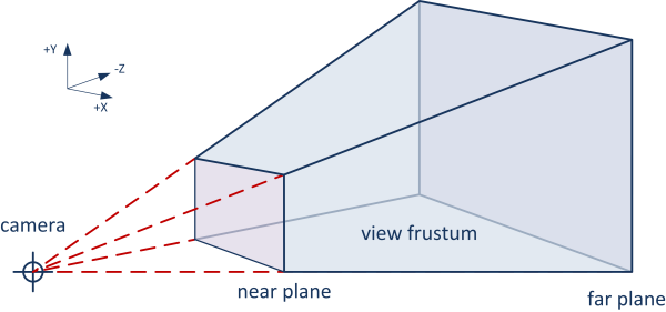
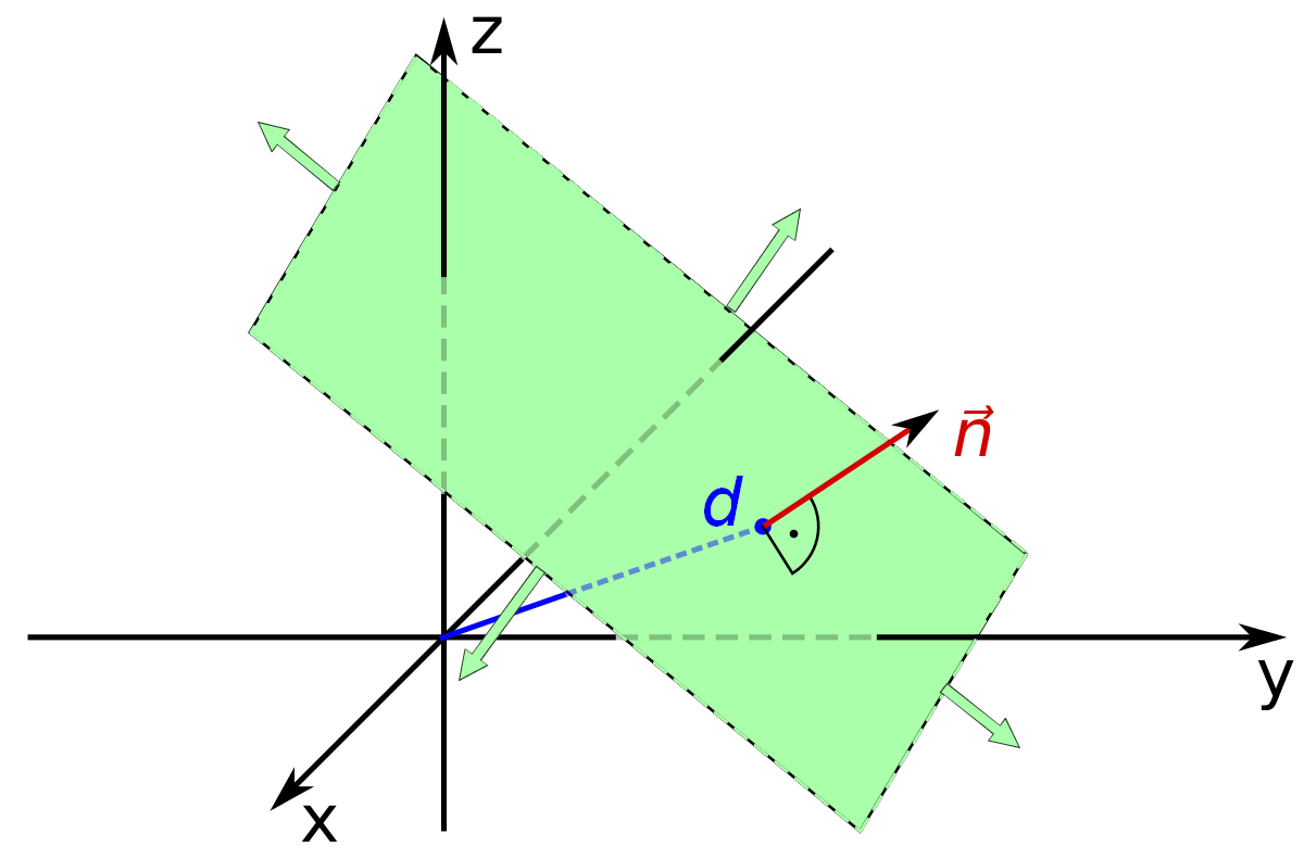
How to mathematically represent a frustum? Thanks to 6 planes: near, far, right, left top and bottom planes. So, an object is visible if it is forward or on the 6 planes. Mathematically a plane is represented with a normal vector and distance to the origin. A plane doesn't have any size or limit as a quad.
So, create a struct to represent a plane:
struct Plane
{
    // unit vector
    glm::vec3 normal = { 0.f, 1.f, 0.f };

    // distance from origin to the nearest point in the plane
    float     distance = 0.f;

    [...]
};
We can now create
struct Frustum
{
    Plane topFace;
    Plane bottomFace;

    Plane rightFace;
    Plane leftFace;

    Plane farFace;
    Plane nearFace;
};
Reminder: a plane can be built with a point and a normal. For the near, the normal is the front vector of the camera. For the far plane, it's the opposite. The normal of the right face we will need to do a cross product. The cross product is the second wonderful tool for the programmer who likes vectors. It allows you to get a perpendicular vector to a plane created with two vectors. To go forward, we need to do the cross product of the right axis per up. We will use it like that:
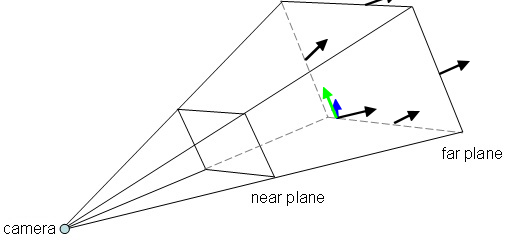
But to know the direction of each vector from the camera to the far plane we will know the side length of the far quad:
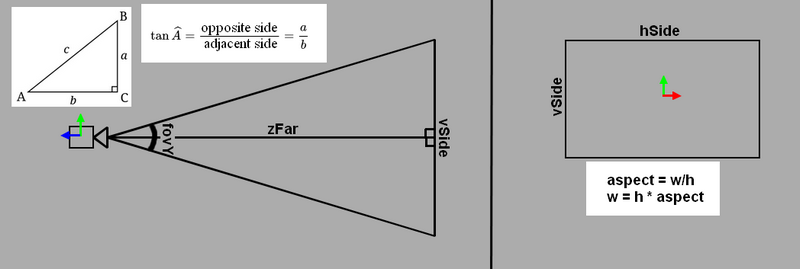
hSide and vSide are the far quad limited by the other planes of the camera frustum. To compute its edge, we will need of trigonometry. As you can see in the image above, we have two rectangle triangles and we can apply the trigonometric functions. So, we would like to obtain vSide which is the opposite side and we have zFar that is the adjacent side of the camera. Tan of fovY is equal to the opposite side (vSide) divided by the adjacent side (zFar). In conclusion, if I move the adjacent side on the left on our equation, tan of fovY multiplied by the zFar is equal to the vSide. We now need to compute hSide. Thanks to the aspect that is a ratio of the width by the height, we can easily obtain it. So, hSide is equal to the vSide multiplied by the aspect as you can see on the right side of the image above. We can now implement our function:
Frustum createFrustumFromCamera(const Camera& cam, float aspect, float fovY,
float zNear, float zFar)
{
Frustum frustum;
const float halfVSide = zFar * tanf(fovY * .5f);
const float halfHSide = halfVSide * aspect;
const glm::vec3 frontMultFar = zFar * cam.Front;
frustum.nearFace = { cam.Position + zNear * cam.Front, cam.Front };
frustum.farFace = { cam.Position + frontMultFar, -cam.Front };
frustum.rightFace = { cam.Position,
glm::cross (frontMultFar - cam.Right * halfHSide, cam.Up) };
frustum.leftFace = { cam.Position,
glm::cross (cam.Up,frontMultFar + cam.Right * halfHSide) };
frustum.topFace = { cam.Position,
glm::cross (cam.Right, frontMultFar - cam.Up * halfVSide) };
frustum.bottomFace = { cam.Position,
glm::cross (frontMultFar + cam.Up * halfVSide, cam.Right) };
return frustum;
}
Bounding volume
Let's take a minute to imagine an algorithm that can detect collisions with your mesh (with all types of polygons in general) and a plane. You will start to say that image is an algorithm that checks if a triangle is on or outside the plane. This algorithm looks pretty and fast! But now imagine that you have hundreds of mesh with thousands of triangles each one. Your algorithm will sign the death of your frame rate fastly. Another method is to wrap your objects in another geometrical object with simplest properties such as a sphere, a box, a capsule... Now our algorithm looks possible without creating a framerate black hole. Its shape is called bounding volume and allows us to create a simpler shape than our mesh to simplify the process. All shapes have their own properties and can correspond plus or minus to our mesh.
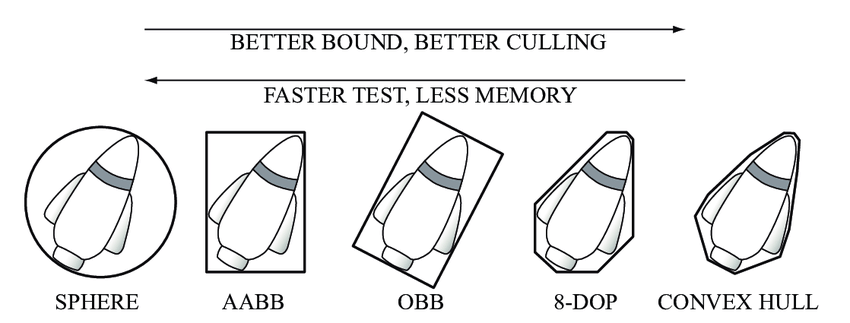
All shapes also have their own compute complexity. The article on Wikipedia is very nice and describes some bounding volumes with their balance and application. In this chapter, we are going to see 2 bounding volumes: the sphere and the AABB. Let's create a simple abstract struct Volume that represent all our bounding volumes:
struct Volume
{
    virtual bool isOnFrustum(const Frustum& camFrustum,
                                            const Transform& modelTransform) const = 0;
};
Sphere
The bounding sphere is the simplest shape to represent a bounding volume. It is represented by center and radius. A sphere is ideal to encapsulate mesh with any rotation. It must be adjusted with the scale and position of the object. We can create struct Sphere that inheritance from volume struct:
struct Sphere : public Volume
{
    glm::vec3 center{ 0.f, 0.f, 0.f };
    float radius{ 0.f };

    [...]
}
This struct doesn't compile because we haven't defined the function isOnFrustum. Let's make it. Remember that our bounding volume is processed thanks to our meshes. That assumes that we will need to apply a transform to our bounding volume to apply it. As we have seen in the previous chapter, we will apply the transformation to a scene graph.
bool isOnFrustum(const Frustum& camFrustum, const Transform& transform) const final
{
    //Get global scale is computed by doing the magnitude of
    //X, Y and Z model matrix's column.
    const glm::vec3 globalScale = transform.getGlobalScale();

    //Get our global center with process it with the global model matrix of our transform
    const glm::vec3 globalCenter{ transform.getModelMatrix() * glm::vec4(center, 1.f) };

    //To wrap correctly our shape, we need the maximum scale scalar.
    const float maxScale = std::max(std::max(globalScale.x, globalScale.y), globalScale.z);

    //Max scale is assuming for the diameter. So, we need the half to apply it to our radius
    Sphere globalSphere(globalCenter, radius * (maxScale * 0.5f));

    //Check Firstly the result that have the most chance
    //to faillure to avoid to call all functions.
    return (globalSphere.isOnOrForwardPlane(camFrustum.leftFace) &&
        globalSphere.isOnOrForwardPlane(camFrustum.rightFace) &&
        globalSphere.isOnOrForwardPlane(camFrustum.farFace) &&
        globalSphere.isOnOrForwardPlane(camFrustum.nearFace) &&
        globalSphere.isOnOrForwardPlane(camFrustum.topFace) &&
        globalSphere.isOnOrForwardPlane(camFrustum.bottomFace));
};
As you can see, we used a function undefined for now called
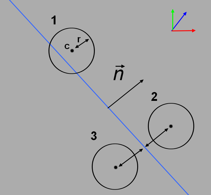
We can see 3 possible cases: Sphere is inside the plane, back or forward. To detect when a sphere is colliding with a plane we need to compute the nearest distance from the center of the sphere to the plane. When we have this distance, we need to compare this distance with radius.
bool isOnOrForwardPlane(const Plane& plane) const
{
    return plane.getSignedDistanceToPlane(center) > -radius;
}
Now we need to create the function
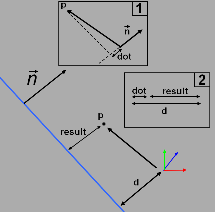
Signed distance is a positive distance from a point if this point is forward the plane. Otherwise this distance will be negative. To obtain it, we will need to call a friend: The dot product. Dot product allows us to obtain the projection from a vector to another. The result of the dot product is a scale and this scalar is a distance. If both vectors go oppositely, the dot product will be negative. Thanks to it, we will obtain the horizontal scale component of a vector in the same direction as the normal of the plane. Next, we will need to subtract this dot product by the nearest distance from the plane to the origin. Hereafter you will find the implementation of this function :
float getSignedDistanceToPlane(const glm::vec3& point) const
{
    return glm::dot(normal, point) - distance;
}
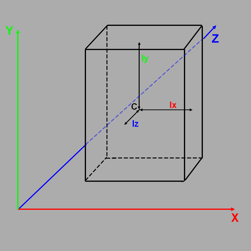
AABB
AABB is the acronym of Axis aligned bounding box. It means that this volume has the same orientation as the world. It can be constructed as different can be we generally create it with its center and its half extension. The half extension is a distance from center to the edge in the direction of an axis. The half extension can be called Ii, Ij, Ik. In this chapter, we will call it Ix, Iy, Iz.
Let's make the base of this structure with few constructors to made its creation the simplest
struct AABB : public BoundingVolume
{
    glm::vec3 center{ 0.f, 0.f, 0.f };
    glm::vec3 extents{ 0.f, 0.f, 0.f };

    AABB(const glm::vec3& min, const glm::vec3& max)
        : BoundingVolume{},
        center{ (max + min) * 0.5f },
        extents{ max.x - center.x, max.y - center.y, max.z - center.z }
    {}

    AABB(const glm::vec3& inCenter, float iI, float iJ, float iK)
        : BoundingVolume{}, center{ inCenter }, extents{ iI, iJ, iK }
    {}

    [...]
};
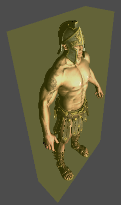
We now need to add the function
To solve this problem lets draw it :
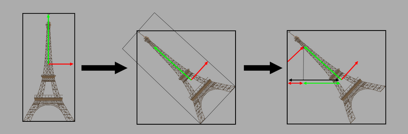
Crazy guys want to rotate our beautiful Eiffel tower but we can see that after its rotation, the AABB is not the same. To make the Shema more readable, assume that referential is not a unit and represented the half extension with the orientation of the mesh. To adjust it, we can see in the third picture that the new extension is the sum of the dot product with the world axis and the scaled referential of our mesh. The problem is seen in 2D but in 3D it's the same thing. Let's implement the function to do it.
bool isOnFrustum(const Frustum& camFrustum, const Transform& transform) const final
{
    //Get global scale thanks to our transform
    const glm::vec3 globalCenter{ transform.getModelMatrix() * glm::vec4(center, 1.f) };

    // Scaled orientation
    const glm::vec3 right = transform.getRight() * extents.x;
    const glm::vec3 up = transform.getUp() * extents.y;
    const glm::vec3 forward = transform.getForward() * extents.z;

    const float newIi = std::abs(glm::dot(glm::vec3{ 1.f, 0.f, 0.f }, right)) +
        std::abs(glm::dot(glm::vec3{ 1.f, 0.f, 0.f }, up)) +
        std::abs(glm::dot(glm::vec3{ 1.f, 0.f, 0.f }, forward));

    const float newIj = std::abs(glm::dot(glm::vec3{ 0.f, 1.f, 0.f }, right)) +
        std::abs(glm::dot(glm::vec3{ 0.f, 1.f, 0.f }, up)) +
        std::abs(glm::dot(glm::vec3{ 0.f, 1.f, 0.f }, forward));

    const float newIk = std::abs(glm::dot(glm::vec3{ 0.f, 0.f, 1.f }, right)) +
        std::abs(glm::dot(glm::vec3{ 0.f, 0.f, 1.f }, up)) +
        std::abs(glm::dot(glm::vec3{ 0.f, 0.f, 1.f }, forward));

    //We not need to divise scale because it's based on the half extention of the AABB
    const AABB globalAABB(globalCenter, newIi, newIj, newIk);

    return (globalAABB.isOnOrForwardPlane(camFrustum.leftFace) &&
        globalAABB.isOnOrForwardPlane(camFrustum.rightFace) &&
        globalAABB.isOnOrForwardPlane(camFrustum.topFace) &&
        globalAABB.isOnOrForwardPlane(camFrustum.bottomFace) &&
        globalAABB.isOnOrForwardPlane(camFrustum.nearFace) &&
        globalAABB.isOnOrForwardPlane(camFrustum.farFace));
};
For the function
bool isOnOrForwardPlane(const Plane& plane) const
{
    // Compute the projection interval radius of b onto L(t) = b.c + t * p.n
    const float r = extents.x * std::abs(plane.normal.x) +
            extents.y * std::abs(plane.normal.y) + extents.z * std::abs(plane.normal.z);

    return -r <= plane.getSignedDistanceToPlane(center);
}
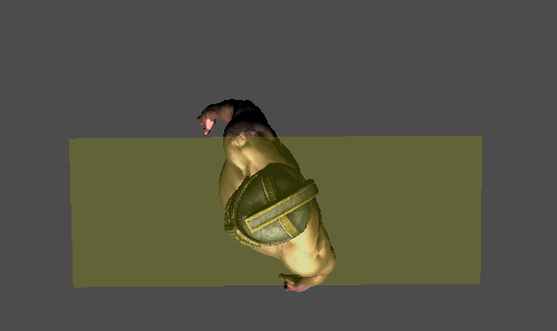
To check if our algorithm works, we need to check that every object disappeared in front of our camera when we moved. Then, we can add a counter that is incremented if an object is displayed and another for the total displayed in our console.
// in main.cpp main lopp
unsigned int total = 0, display = 0;
ourEntity.drawSelfAndChild(camFrustum, ourShader, display, total);
std::cout << "Total process in CPU : " << total;
std::cout << " / Total send to GPU : " << display << std::endl;

// In the drawSelfAndChild function of entity
void drawSelfAndChild(const Frustum& frustum, Shader& ourShader,
                                            unsigned int& display, unsigned int& total)
{
    if (boundingVolume->isOnFrustum(frustum, transform))
    {
        ourShader.setMat4("model", transform.getModelMatrix());
        pModel->Draw(ourShader);
        display++;
    }
    total++;

    for (auto&& child : children)
    {
        child->drawSelfAndChild(frustum, ourShader, display, total);
    }
}
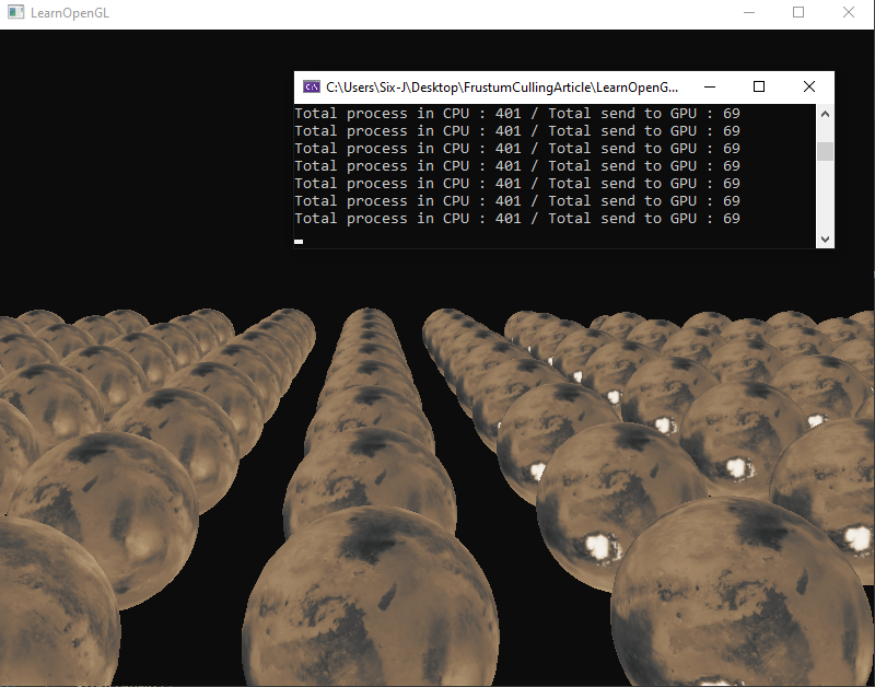
Ta-dah ! The average of objects sent to our GPUrepresents now about 15% of the total and is only divided by 6. A wonderful result if your GPU process is the bottleneck because of your shader or number of polygons. You can find the code here.
Optimization
Now you know how to make your frustum culling. Frustum culling can be useful to avoid computation of things that are not visible. You can use it to not compute the animation state of your entity, simplify its AI... For this reason, I advise you to add a IsInFrustum flag in your entity and do a frustum culling pass that fills this variable.
Space partitionning
In our example, frustum culling is a good balance with a small number of entities in the CPU.
If you want to optimize your detection, you now will need to partition your space.
To do it, a lot of algorithms exist and each has interesting properties which depend on your usage :
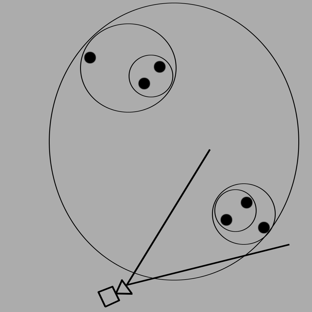
- BSH (Bounding sphere hierarchy or tree) :
Different kinds exist. The simplest implementation is to wrap both nearest objects in a sphere.
Wrap this sphere with another group or objetc etc...
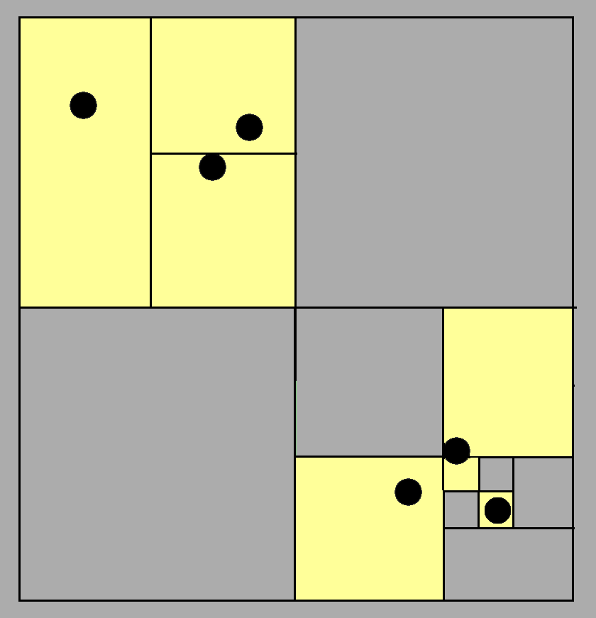
- Quadtree :
The main idea is that you will split space into 4 zones that can be split into four zones etc... until an object wasn't wrapped alone.
Your object will be the leaf of this diagram.
The quadtree is very nice to partition 2D spaces but also if you don't need to partition height. It can be very useful in strategy games like 4x (like age of empire, war selection...) because you don't need height partitioning.
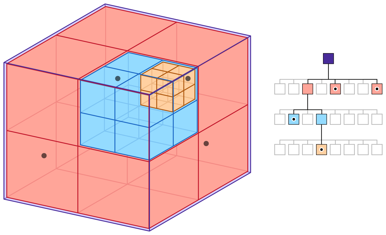
 - Octree :
It's like a quadtree but with 8 nodes. It's nice if you have a 3D game with elements in different height levels.
- Octree :
It's like a quadtree but with 8 nodes. It's nice if you have a 3D game with elements in different height levels.
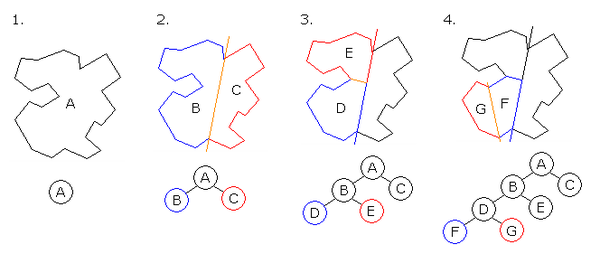
 - BSP (binary space partitioning) :
It's a very fast algorithm that allows you to split space with segments. You will define a segment and the algorithm will sort if an object is in front of this segment or behind.
It's very useful with a map, city, dungeon... The segments can be created at the same time if you generate a map and can be fast forward.
- BSP (binary space partitioning) :
It's a very fast algorithm that allows you to split space with segments. You will define a segment and the algorithm will sort if an object is in front of this segment or behind.
It's very useful with a map, city, dungeon... The segments can be created at the same time if you generate a map and can be fast forward.
 - Lot of other methods exist, be curious.
I don't implement each of these methods, I just learn it to know that they exist if one day I need specific space partitioning.
Some algorithm is great to parallelize like octree of quadtree if you use multithread and must also balance on your decision.
- Lot of other methods exist, be curious.
I don't implement each of these methods, I just learn it to know that they exist if one day I need specific space partitioning.
Some algorithm is great to parallelize like octree of quadtree if you use multithread and must also balance on your decision.
Compute shader
Compute shader allows you to process computation on shader. This technique must be used only if you have a high parallelized task like check collision with a simple list of bounds. I never implemented this technique for the frustum culling but it can be used in this case to avoid updating space partitioning if you have a lot of objects that move.
Additional resources
- Article about camera frustum extraction: Fast Extraction of Viewing Frustum Planes from the WorldView-Projection Matrix by Gil Gribb and Klaus Hartmann
- Article about collisions detection: A wonderful resource for collision detection and another approach about volume, culling and mathematic concept
- Article to go further: A good article to go further on GPU culling process, multithreading and OBB
Autor
Contact: e-mail
Date: 09/2021