


CSM
Guest-Articles/2021/CSM
Cascaded Shadow Mapping
Shadow mapping as described on LearnOpenGL is a powerful, and relatively simple technique. However, if implemented as-is from the above referred tutorial, the avid OpenGL student will notice a few shortcomings.
- The shadow map is always created around the origin, and not on the area the camera is actually looking at. It would be best of course if we could shadow map the whole scene, with sufficient resolution, but on current hardware this is not feasible. In reality we want the shadow maps to be created on objects that are in view, saving our precious GPU memory for things that matter.
- The shadow map orthographic projection matrix is not properly fitted onto the view frustum. To achieve the best possible resolution for our shadow maps, the ortho matrix needs to be as tightly fit to the camera frustum as possible, because again: if it’s larger that means that less detail is spent on the objects that are actually visible.
- The shadow maps (even with advanced PCF functions) are blurry if we want the shadow rendering distance to be large, as we would in a game with a first-person camera. We can increase the resolution of the shadow maps to mitigate this, but GPU memory is a resource we should be conservative of.
Cascaded shadow mapping is a direct answer to the third point, however while implementing it we will solve the first two points, too. The core insight in cascaded shadow mapping is, that we don’t need the same amount of shadow detail for things that are far from us. We want crisp shadows for stuff that’s near to the near plane, and we are absolutely fine with blurriness for objects that are hundreds of units away: it’s not going to be noticeable at all. How can we achieve this? The answer is beautiful in its simplicity: just render different shadow maps for things that are close and for those that are far away, and sample from them according to the depth of the fragment in the fragment shader. The high-level algorithm is as follows:
- Divide our ordinary view frustum into n subfrusta, where the far plane of the
i-th frustum is the near plane of the(i+1)-th frustum - Compute the tightly fitting ortho matrix for each frustum
- For each frustum render a shadow map as if seen from our directional light
- Send all shadow maps to our fragment shader
- Render the scene, and according to the fragment’s depth value sample from the correct shadow map
Sounds simple right? Well, it is, but as it often is when it comes to our friend OpenGL: the devil is in the details.
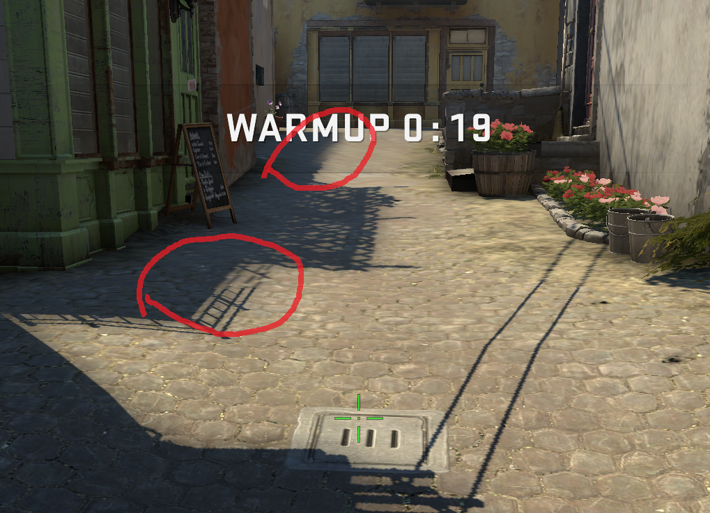
In the above image we can see the edges of shadow cascades in Counter-Strike: Global Offensive. The image was captured on low graphics settings.
World coordinates of the view frustum
Before getting our hands dirty with shadows, we need to tackle a more abstract problem: making our projection matrix fit nicely onto a generic frustum. To be able to do this, we need to know the world space coordinates of the frustum in question. While this might sound daunting at first, we already have all the tools necessary in our repertoire. If we think back on the excellent coordinate systems tutorial, the beheaded pyramid of the frustum only looks that way in world coordinates, and our view and projection matrices do the job of transforming this unusual shape into the NDC cube. And we know the coordinates of the corners of the NDC cube: the coordinates are in the range [-1,1] on the three axes. Because matrix multiplication is a reversible process, we can apply the inverse of the view and projection matrices on the corner points of the NDC cube to get the frustum corners in world space.
std::vector<glm::vec4> getFrustumCornersWorldSpace(const glm::mat4& proj, const glm::mat4& view)
{
    const auto inv = glm::inverse(proj * view);

    std::vector<glm::vec4> frustumCorners;
    for (unsigned int x = 0; x < 2; ++x)
    {
        for (unsigned int y = 0; y < 2; ++y)
        {
            for (unsigned int z = 0; z < 2; ++z)
            {
                const glm::vec4 pt =
                    inv * glm::vec4(
                        2.0f * x - 1.0f,
                        2.0f * y - 1.0f,
                        2.0f * z - 1.0f,
                        1.0f);
                frustumCorners.push_back(pt / pt.w);
            }
        }
    }

    return frustumCorners;
}
The projection matrix described here is a perspective matrix, using the camera’s aspect ratio and fov, and using the near and far plane of the current frustum being analyzed. The view matrix is the view matrix of our camera.
const auto proj = glm::perspective (
glm::radians (camera.Zoom),
(float)SCR_WIDTH / (float)SCR_HEIGHT,
nearPlane,
farPlane
);
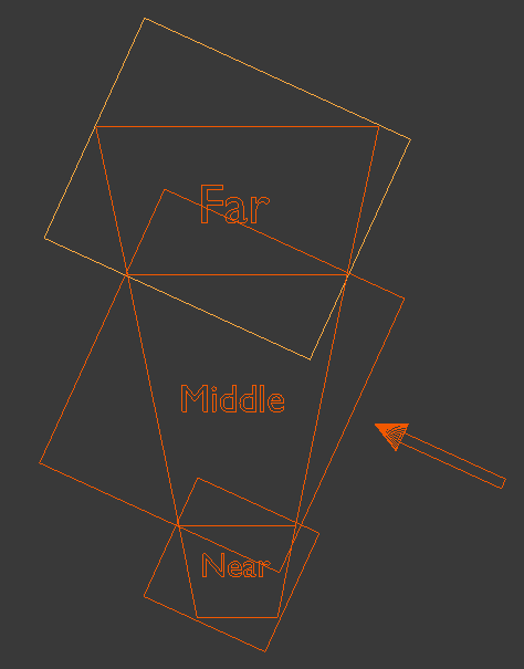
The above image is the courtesy of OGLDev
The light view-projection matrix
This matrix - as in ordinary shadow mapping – is the product of the view and projection matrix that transforms the scene as if it were seen by the light. Calculating the view matrix is simple, we know the direction our light is coming from, and we know a point in world space that it definitely is looking at: the center of the frustum. The position of the frustum center can be obtained by averaging the coordinates of the frustum corners. (This is so because averaging the coordinates of the near and far plane gives us the center of those rectangles, and taking the midpoint of these two points gives us the center of the frustum.)
glm::vec3 center = glm::vec3(0, 0, 0);
for (const auto& v : corners)
{
center += glm::vec3(v);
}
center /= corners.size();
const auto lightView = glm::lookAt (
center + lightDir,
center,
glm::vec3(0.0f, 1.0f, 0.0f)
);
The projection matrix is bit more complex. Because the light in question is a directional light, the matrix needs to be an orthographic projection matrix, this much is clear. To understand how we determine the left, right, top etc. parameters of the matrix imagine the scene you are drawing from the perspective of the light. From this viewpoint the shadow map we are trying to render is going to be an axis aligned rectangle, and this rectangle – as we established before – needs to fit on the frustum tightly. So we need to obtain the coordinates of the frustum in this space, and take the maximum and minimum of the coordinates along the coordinate axes. While this might sound daunting at first, this perspective is exactly what our light view matrix transformation gives us. We need to transform the frustum corner points in the light view space, and find the maximum and minimum coordinates.
float minX = std::numeric_limits<float>::max();
float maxX = std::numeric_limits<float>::lowest();
float minY = std::numeric_limits<float>::max();
float maxY = std::numeric_limits<float>::lowest();
float minZ = std::numeric_limits<float>::max();
float maxZ = std::numeric_limits<float>::lowest();
for (const auto& v : corners)
{
    const auto trf = lightView * v;
    minX = std::min(minX, trf.x);
    maxX = std::max(maxX, trf.x);
    minY = std::min(minY, trf.y);
    maxY = std::max(maxY, trf.y);
    minZ = std::min(minZ, trf.z);
    maxZ = std::max(maxZ, trf.z);
}
We are going to create our projection matrix from the product of two matrices. First, we are going to create an ortho projection matrix, with the left, right, top, bottom parameters set to -1 or 1, and the z values set to minZ and maxZ. This creates a 3D rectangle sitting on the origin with width and height of 2, and depth of (maxZ – minZ). In the code we increase the amount of space covered by minZ and maxZ by multiplying or dividing them with a zMult. This is because we want to include geometry which is behind or in front of our frustum in camera space. Think about it: not only geometry which is in the frustum can cast shadows on a surface in the frustum!
Before creating the actual projection matrix we are going to increase the size of the space covered by the near and far plane of the light frustum. We do this by "pulling back" the near plane, and "pushing away" the far plane. In the code we achieve this by dividing or multiplying by zMult. This is because we want to include geometry which is behind or in front of our frustum in camera space. Think about it: not only geometry which is in the frustum can cast shadows on a surface in the frustum!
// Tune this parameter according to the scene
constexpr float zMult = 10.0f;
if (minZ < 0)
{
minZ *= zMult;
}
else
{
minZ /= zMult;
}
if (maxZ < 0)
{
maxZ /= zMult;
}
else
{
maxZ *= zMult;
}
const glm::mat4 lightProjection = glm::ortho (minX, maxX, minY, maxY, minZ, maxZ);
return lightProjection * lightView;
Multiplying the view and projection matrices together, we get the view-projection matrix of the light for the given frustum. We need to do this procedure for every frustum in our cascade.
2D array textures
While we let our stomachs digest what we learned about frustum fitting we should figure out how to store our shadow maps. In principle there is no limit on how many cascades we can do, so hardcoding an arbitrary value doesn’t seem like a wise idea. Also, it quickly becomes tiresome typing out and binding sampler2Ds for our shaders. OpenGL has a good solution to this problem in the form of
uniform sampler2DArray shadowMap;
To sample from them we can use the regular texture function with a vec3 parameter for texture coordinates, the third dimension specifying which layer to sample from, starting from 0.
texture(depthMap, vec3(TexCoords, currentLayer))
Creating our array texture is slightly different than creating a regular old texture2D. Instead of
glGenFramebuffers (1, &lightFBO);
glGenTextures (1, &lightDepthMaps);
glBindTexture (GL_TEXTURE_2D_ARRAY, lightDepthMaps);
glTexImage3D(
GL_TEXTURE_2D_ARRAY,
0,
GL_DEPTH_COMPONENT32F,
depthMapResolution,
depthMapResolution,
int(shadowCascadeLevels.size()) + 1,
0,
GL_DEPTH_COMPONENT,
GL_FLOAT,
nullptr);
glTexParameter i(GL_TEXTURE_2D_ARRAY, GL_TEXTURE_MIN_FILTER, GL_NEAREST);
glTexParameter i(GL_TEXTURE_2D_ARRAY, GL_TEXTURE_MAG_FILTER, GL_NEAREST);
glTexParameter i(GL_TEXTURE_2D_ARRAY, GL_TEXTURE_WRAP_S, GL_CLAMP_TO_BORDER);
glTexParameter i(GL_TEXTURE_2D_ARRAY, GL_TEXTURE_WRAP_T, GL_CLAMP_TO_BORDER);
constexpr float bordercolor[] = { 1.0f, 1.0f, 1.0f, 1.0f };
glTexParameter fv(GL_TEXTURE_2D_ARRAY, GL_TEXTURE_BORDER_COLOR, bordercolor);
glBindFramebuffer (GL_FRAMEBUFFER, lightFBO);
glFramebufferTexture(GL_FRAMEBUFFER, GL_DEPTH_ATTACHMENT, lightDepthMaps, 0);
glDrawBuffer(GL_NONE);
glReadBuffer(GL_NONE);
int status = glCheckFramebufferStatus (GL_FRAMEBUFFER);
if (status != GL_FRAMEBUFFER_COMPLETE)
{
std::cout << "ERROR::FRAMEBUFFER:: Framebuffer is not complete!";
throw 0;
}
glBindFramebuffer (GL_FRAMEBUFFER, 0);
Take care when binding this texture to a sampler. Again: we need to use GL_TEXTURE_2D_ARRAY as the target parameter.
glActiveTexture (GL_TEXTURE1);
glBindTexture (GL_TEXTURE_2D_ARRAY, lightDepthMaps);
So far so good, now we know the semantics of using a texture array. It all seems straightforward, but OpenGL has one more curveball to throw at us: we can’t render into this texture the ordinary way, we need to do something called
#version 460 core
layout (location = 0) in vec3 aPos;

uniform mat4 model;

void main()
{
    gl_Position = model * vec4(aPos, 1.0);
}
The newly inserted geometry shader will look something like this:
#version 460 core

layout(triangles, invocations = 5) in;
layout(triangle_strip, max_vertices = 3) out;

layout (std140, binding = 0) uniform LightSpaceMatrices
{
    mat4 lightSpaceMatrices[16];
};

void main()
{
    for (int i = 0; i < 3; ++i)
    {
        gl_Position =
            lightSpaceMatrices[gl_InvocationID] * gl_in[i].gl_Position;
        gl_Layer = gl_InvocationID;
        EmitVertex();
    }
    EndPrimitive();
}
The input declaration has a new member, specifying the
The fragment shader remains the same empty, passthrough shader.
#version 460 core

void main()
{
}
Our draw call invoking the shader looks something like this:
simpleDepthShader.use();
glBindFramebuffer (GL_FRAMEBUFFER, lightFBO);
glFramebufferTexture(GL_FRAMEBUFFER, GL_TEXTURE_2D_ARRAY, lightDepthMaps, 0);
glViewport (0, 0, depthMapResolution, depthMapResolution);
glClear (GL_DEPTH_BUFFER_BIT);
glCullFace (GL_FRONT); // peter panning
renderScene(simpleDepthShader);
glCullFace (GL_BACK);
glBindFramebuffer (GL_FRAMEBUFFER, 0);
Scene rendering
Now the only thing remaining is doing the actual shadow rendering. In our ordinary phong/deferred fragment shader where we calculate whether the current fragment is occluded or not, we need to insert some logic to decide which light space matrix to use, and which texture to sample from.
// select cascade layer
vec4 fragPosViewSpace = view * vec4(fragPosWorldSpace, 1.0);
float depthValue = abs(fragPosViewSpace.z);

int layer = -1;
for (int i = 0; i < cascadeCount; ++i)
{
    if (depthValue < cascadePlaneDistances[i])
    {
        layer = i;
        break;
    }
}
if (layer == -1)
{
    layer = cascadeCount;
}

vec4 fragPosLightSpace = lightSpaceMatrices[layer] * vec4(fragPosWorldSpace, 1.0);
If you remember to prevent shadow acne we applied a depth bias to our image. We need to do the same here, but keep in mind that we are dealing with multiple shadow maps, and on each of them the pixels cover a widely different amount of space, and a unit increase in pixel value means different depth increase in all of them. Because of this we need to apply a different bias depending on which shadow map we sample from. In my experience scaling the bias inversely proportionally with the far plane works nicely.
// perform perspective divide
vec3 projCoords = fragPosLightSpace.xyz / fragPosLightSpace.w;
// transform to [0,1] range
projCoords = projCoords * 0.5 + 0.5;

// get depth of current fragment from light's perspective
float currentDepth = projCoords.z;
if (currentDepth  > 1.0)
{
    return 0.0;
}
// calculate bias (based on depth map resolution and slope)
vec3 normal = normalize(fs_in.Normal);
float bias = max(0.05 * (1.0 - dot(normal, lightDir)), 0.005);
if (layer == cascadeCount)
{
    bias *= 1 / (farPlane * 0.5f);
}
else
{
    bias *= 1 / (cascadePlaneDistances[layer] * 0.5f);
}
The rest of the function is the same as before, the only difference is that we are sampling from a 2D array texture, hence we need to add a third parameter to the
// PCF
float shadow = 0.0;
vec2 texelSize = 1.0 / vec2(textureSize(shadowMap, 0));
for(int x = -1; x <= 1; ++x)
{
    for(int y = -1; y <= 1; ++y)
    {
        float pcfDepth = texture(
                    shadowMap,
                    vec3(projCoords.xy + vec2(x, y) * texelSize,
                    layer)
                    ).r;
        shadow += (currentDepth - bias) > pcfDepth ? 1.0 : 0.0;
    }
}
shadow /= 9.0;

// keep the shadow at 0.0 when outside the far_plane region of the light's frustum.
if(projCoords.z > 1.0)
{
    shadow = 0.0;
}

return shadow;
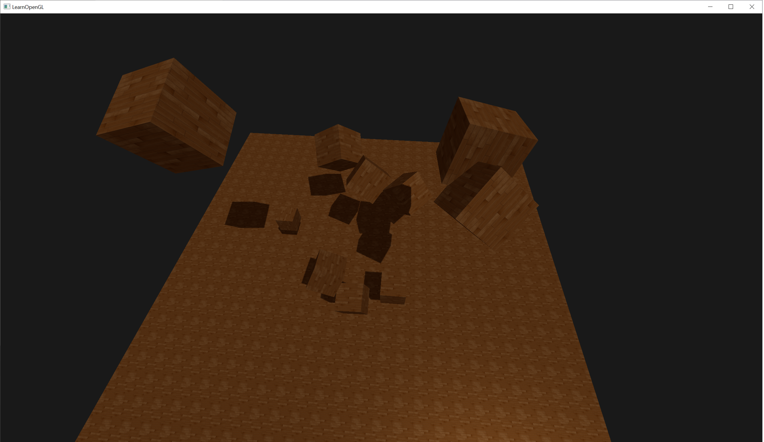
And that's it! If we did everything correctly we should see that the renderer switches between shadow maps based on the distance. Try setting some unreasonable cascade plane distances (for example only one, which is a few units from the camera) to see if the code really does work. You should see a noticable degradation in shadow quality between the two sides of the plane. If you see moire artifacts on the screen try changing around bias parameters a bit.
You can find the full source code for the cascaded shadow mapping demo here.
Closing thoughts
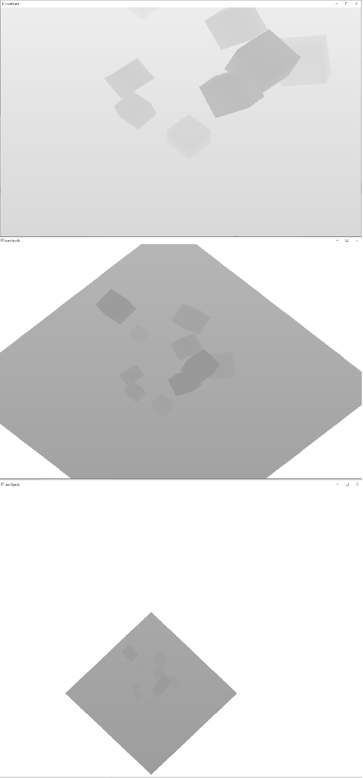
In the sample project provided you can toggle depthmap visualization by pressing F. When in depthmap visualization mode you can press the + key to swap between the different layers.
When browsing through the code you might wonder why is the UBO array length 16. This is just an arbitrary choice, to me it seemed unlikely that anyone would use more than 16 shadow cascades, so this seemed like a nice number to allocate.
In the code example the cube positions and rotations are randomized. If you want to try the example with static geometry I suggest you seed the random number generator.
If you are going through the sources given below you might notice that the NVIDIA article is tackling the light projection matrix creation in a roundabout way compared to what is given in this article. However, what they are doing is mathematically equivalent to what we are doing in respect to the x-y coordinates in light view space, which is what matters. This can be seen by plugging stuff into the matrix given in this article by songho.
Additional Resources
- NVIDIA paper on the subject: incomprehensible in my opinion but has to be mentioned
- A series of incredibly helpful and useful forum posts
- Another interesting tutorial from OGLDev
- An article from Microsoft: nice pictures illustrating some issues with CSM
- An article about shadow bias
- Some informative drawings about shadow bias strategies
Website for geolocation enthusiasts: GeoDetective