


Camera
Getting-Started/Camera
In the previous chapter we discussed the view matrix and how we can use the view matrix to move around the scene (we moved backwards a little). OpenGL by itself is not familiar with the concept of a camera, but we can try to simulate one by moving all objects in the scene in the reverse direction, giving the illusion that we are moving.
In this chapter we'll discuss how we can set up a camera in OpenGL. We will discuss a fly style camera that allows you to freely move around in a 3D scene. We'll also discuss keyboard and mouse input and finish with a custom camera class.
Camera/View space
When we're talking about camera/view space we're talking about all the vertex coordinates as seen from the camera's perspective as the origin of the scene: the view matrix transforms all the world coordinates into view coordinates that are relative to the camera's position and direction. To define a camera we need its position in world space, the direction it's looking at, a vector pointing to the right and a vector pointing upwards from the camera. A careful reader may notice that we're actually going to create a coordinate system with 3 perpendicular unit axes with the camera's position as the origin.
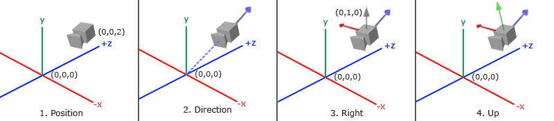
1. Camera position
Getting the camera position is easy. The camera position is a vector in world space that points to the camera's position. We set the camera at the same position we've set the camera in the previous chapter:
glm::vec3 cameraPos = glm::vec3(0.0f, 0.0f, 3.0f);
2. Camera direction
The next vector required is the camera's direction e.g. at what direction it is pointing at. For now we let the camera point to the origin of our scene: (0,0,0). Remember that if we subtract two vectors from each other we get a vector that's the difference of these two vectors? Subtracting the camera position vector from the scene's origin vector thus results in the direction vector we want. For the view matrix's coordinate system we want its z-axis to be positive and because by convention (in OpenGL) the camera points towards the negative z-axis we want to negate the direction vector. If we switch the subtraction order around we now get a vector pointing towards the camera's positive z-axis:
glm::vec3 cameraTarget = glm::vec3(0.0f, 0.0f, 0.0f);
glm::vec3 cameraDirection = glm::normalize(cameraPos - cameraTarget);
3. Right axis
The next vector that we need is a right vector that represents the positive x-axis of the camera space. To get the right vector we use a little trick by first specifying an up vector that points upwards (in world space). Then we do a cross product on the up vector and the direction vector from step 2. Since the result of a cross product is a vector perpendicular to both vectors, we will get a vector that points in the positive x-axis's direction (if we would switch the cross product order we'd get a vector that points in the negative x-axis):
glm::vec3 up = glm::vec3(0.0f, 1.0f, 0.0f);
glm::vec3 cameraRight = glm::normalize(glm::cross (up, cameraDirection));
4. Up axis
Now that we have both the x-axis vector and the z-axis vector, retrieving the vector that points to the camera's positive y-axis is relatively easy: we take the cross product of the right and direction vector:
glm::vec3 cameraUp = glm::cross (cameraDirection, cameraRight);
With the help of the cross product and a few tricks we were able to create all the vectors that form the view/camera space. For the more mathematically inclined readers, this process is known as the Gram-Schmidt process in linear algebra. Using these camera vectors we can now create a
Look At
A great thing about matrices is that if you define a coordinate space using 3 perpendicular (or non-linear) axes you can create a matrix with those 3 axes plus a translation vector and you can transform any vector to that coordinate space by multiplying it with this matrix. This is exactly what the LookAt matrix does and now that we have 3 perpendicular axes and a position vector to define the camera space we can create our own LookAt matrix: \[LookAt = \begin{bmatrix} \color{red}{R_x} & \color{red}{R_y} & \color{red}{R_z} & 0 \\ \color{green}{U_x} & \color{green}{U_y} & \color{green}{U_z} & 0 \\ \color{blue}{D_x} & \color{blue}{D_y} & \color{blue}{D_z} & 0 \\ 0 & 0 & 0 & 1 \end{bmatrix} * \begin{bmatrix} 1 & 0 & 0 & -\color{purple}{P_x} \\ 0 & 1 & 0 & -\color{purple}{P_y} \\ 0 & 0 & 1 & -\color{purple}{P_z} \\ 0 & 0 & 0 & 1 \end{bmatrix} \] Where \(\color{red}R\) is the right vector, \(\color{green}U\) is the up vector, \(\color{blue}D\) is the direction vector and \(\color{purple}P\) is the camera's position vector. Note that the rotation (left matrix) and translation (right matrix) parts are inverted (transposed and negated respectively) since we want to rotate and translate the world in the opposite direction of where we want the camera to move. Using this LookAt matrix as our view matrix effectively transforms all the world coordinates to the view space we just defined. The LookAt matrix then does exactly what it says: it creates a view matrix that looks at a given target.
Luckily for us, GLM already does all this work for us. We only have to specify a camera position, a target position and a vector that represents the up vector in world space (the up vector we used for calculating the right vector). GLM then creates the LookAt matrix that we can use as our view matrix:
glm::mat4 view;
view = glm::lookAt (glm::vec3(0.0f, 0.0f, 3.0f),
glm::vec3(0.0f, 0.0f, 0.0f),
glm::vec3(0.0f, 1.0f, 0.0f));
The
Before delving into user input, let's get a little funky first by rotating the camera around our scene. We keep the target of the scene at (0,0,0). We use a little bit of trigonometry to create an x and z coordinate each frame that represents a point on a circle and we'll use these for our camera position. By re-calculating the x and y coordinate over time we're traversing all the points in a circle and thus the camera rotates around the scene. We enlarge this circle by a pre-defined radius and create a new view matrix each frame using GLFW's
const float radius = 10.0f;
float camX = sin(glfwGetTime ()) * radius;
float camZ = cos(glfwGetTime ()) * radius;
glm::mat4 view;
view = glm::lookAt (glm::vec3(camX, 0.0, camZ), glm::vec3(0.0, 0.0, 0.0), glm::vec3(0.0, 1.0, 0.0));
If you run this code you should get something like this:
With this little snippet of code the camera now circles around the scene over time. Feel free to experiment with the radius and position/direction parameters to get the feel of how this LookAt matrix works. Also, check the source code if you're stuck.
Walk around
Swinging the camera around a scene is fun, but it's more fun to do all the movement ourselves! First we need to set up a camera system, so it is useful to define some camera variables at the top of our program:
glm::vec3 cameraPos   = glm::vec3(0.0f, 0.0f,  3.0f);
glm::vec3 cameraFront = glm::vec3(0.0f, 0.0f, -1.0f);
glm::vec3 cameraUp    = glm::vec3(0.0f, 1.0f,  0.0f);
The LookAt function now becomes:
view = glm::lookAt (cameraPos, cameraPos + cameraFront, cameraUp);
First we set the camera position to the previously defined cameraPos. The direction is the current position + the direction vector we just defined. This ensures that however we move, the camera keeps looking at the target direction. Let's play a bit with these variables by updating the cameraPos vector when we press some keys.
We already defined a
void processInput(GLFWwindow *window)
{
...
const float cameraSpeed = 0.05f; // adjust accordingly
if (glfwGetKey(window, GLFW_KEY_W) == GLFW_PRESS)
cameraPos += cameraSpeed * cameraFront;
if (glfwGetKey(window, GLFW_KEY_S) == GLFW_PRESS)
cameraPos -= cameraSpeed * cameraFront;
if (glfwGetKey(window, GLFW_KEY_A) == GLFW_PRESS)
cameraPos -= glm::normalize(glm::cross (cameraFront, cameraUp)) * cameraSpeed;
if (glfwGetKey(window, GLFW_KEY_D) == GLFW_PRESS)
cameraPos += glm::normalize(glm::cross (cameraFront, cameraUp)) * cameraSpeed;
}
Whenever we press one of the WASD keys, the camera's position is updated accordingly. If we want to move forward or backwards we add or subtract the direction vector from the position vector scaled by some speed value. If we want to move sideways we do a cross product to create a right vector and we move along the right vector accordingly. This creates the familiar
By now, you should already be able to move the camera somewhat, albeit at a speed that's system-specific so you may need to adjust cameraSpeed.
Movement speed
Currently we used a constant value for movement speed when walking around. In theory this seems fine, but in practice people's machines have different processing powers and the result of that is that some people are able to render much more frames than others each second. Whenever a user renders more frames than another user he also calls
Graphics applications and games usually keep track of a
To calculate the deltaTime value we keep track of 2 global variables:
float deltaTime = 0.0f;	// Time between current frame and last frame
float lastFrame = 0.0f; // Time of last frame
Within each frame we then calculate the new deltaTime value for later use:
float currentFrame = glfwGetTime ();
deltaTime = currentFrame - lastFrame;
lastFrame = currentFrame;
Now that we have deltaTime we can take it into account when calculating the velocities:
void processInput(GLFWwindow *window)
{
    float cameraSpeed = 2.5f * deltaTime;
    [...]
}
Since we're using deltaTime the camera will now move at a constant speed of 2.5 units per second. Together with the previous section we should now have a much smoother and more consistent camera system for moving around the scene:
And now we have a camera that walks and looks equally fast on any system. Again, check the source code if you're stuck. We'll see the deltaTime value frequently return with anything movement related.
Look around
Only using the keyboard keys to move around isn't that interesting. Especially since we can't turn around making the movement rather restricted. That's where the mouse comes in!
To look around the scene we have to change the cameraFront vector based on the input of the mouse. However, changing the direction vector based on mouse rotations is a little complicated and requires some trigonometry. If you do not understand the trigonometry, don't worry, you can just skip to the code sections and paste them in your code; you can always come back later if you want to know more.
Euler angles
Euler angles are 3 values that can represent any rotation in 3D, defined by Leonhard Euler somewhere in the 1700s. There are 3 Euler angles: pitch, yaw and roll. The following image gives them a visual meaning:
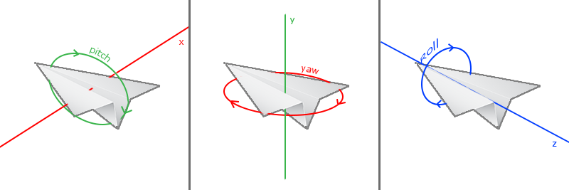
The
For our camera system we only care about the yaw and pitch values so we won't discuss the roll value here. Given a pitch and a yaw value we can convert them into a 3D vector that represents a new direction vector. The process of converting yaw and pitch values to a direction vector requires a bit of trigonometry. and we start with a basic case:
Let's start with a bit of a refresher and check the general right triangle case (with one side at a 90 degree angle):
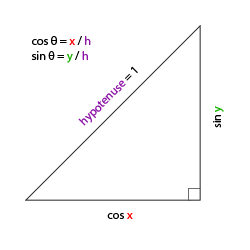
If we define the hypotenuse to be of length 1 we know from trigonometry (soh cah toa) that the adjacant side's length is \(\cos \ \color{red}x/\color{purple}h = \cos \ \color{red}x/\color{purple}1 = \cos\ \color{red}x\) and that the opposing side's length is \(\sin \ \color{green}y/\color{purple}h = \sin \ \color{green}y/\color{purple}1 = \sin\ \color{green}y\). This gives us some general formulas for retrieving the length in both the x and y sides on right triangles, depending on the given angle. Let's use this to calculate the components of the direction vector.
Let's imagine this same triangle, but now looking at it from a top perspective with the adjacent and opposite sides being parallel to the scene's x and z axis (as if looking down the y-axis).
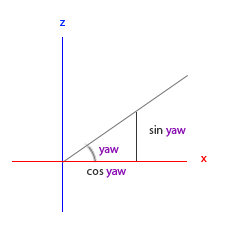
If we visualize the yaw angle to be the counter-clockwise angle starting from the x side we can see that the length of the x side relates to cos(yaw). And similarly how the length of the z side relates to sin(yaw).
If we take this knowledge and a given yaw value we can use it to create a camera direction vector:
glm::vec3 direction;
direction.x = cos(glm::radians (yaw)); // Note that we convert the angle to radians first
direction.z = sin(glm::radians (yaw));
This solves how we can get a 3D direction vector from a yaw value, but pitch needs to be included as well. Let's now look at the y axis side as if we're sitting on the xz plane:
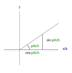
Similarly, from this triangle we can see that the direction's y component equals sin(pitch) so let's fill that in:
direction.y = sin(glm::radians (pitch));
However, from the pitch triangle we can also see the xz sides are influenced by cos(pitch) so we need to make sure this is also part of the direction vector. With this included we get the final direction vector as translated from yaw and pitch Euler angles:
direction.x = cos(glm::radians (yaw)) * cos(glm::radians (pitch));
direction.y = sin(glm::radians (pitch));
direction.z = sin(glm::radians (yaw)) * cos(glm::radians (pitch));
This gives us a formula to convert yaw and pitch values to a 3-dimensional direction vector that we can use for looking around.
We've set up the scene world so everything's positioned in the direction of the negative z-axis. However, if we look at the x and z yaw triangle we see that a \(\theta\) of 0 results in the camera's direction vector to point towards the positive x-axis. To make sure the camera points towards the negative z-axis by default we can give the yaw a default value of a 90 degree clockwise rotation. Positive degrees rotate counter-clockwise so we set the default yaw value to:
yaw = -90.0f;
You've probably wondered by now: how do we set and modify these yaw and pitch values?
Mouse input
The yaw and pitch values are obtained from mouse (or controller/joystick) movement where horizontal mouse-movement affects the yaw and vertical mouse-movement affects the pitch. The idea is to store the last frame's mouse positions and calculate in the current frame how much the mouse values changed. The higher the horizontal or vertical difference, the more we update the pitch or yaw value and thus the more the camera should move.
First we will tell GLFW that it should hide the cursor and
glfwSetInputMode(window, GLFW_CURSOR, GLFW_CURSOR_DISABLED);
After this call, wherever we move the mouse it won't be visible and it should not leave the window. This is perfect for an FPS camera system.
To calculate the pitch and yaw values we need to tell GLFW to listen to mouse-movement events. We do this by creating a callback function with the following prototype:
void mouse_callback(GLFWwindow* window, double xpos, double ypos);
Here xpos and ypos represent the current mouse positions. As soon as we register the callback function with GLFW each time the mouse moves, the
glfwSetCursorPosCallback(window, mouse_callback);
When handling mouse input for a fly style camera there are several steps we have to take before we're able to fully calculate the camera's direction vector:
- Calculate the mouse's offset since the last frame.
- Add the offset values to the camera's yaw and pitch values.
- Add some constraints to the minimum/maximum pitch values.
- Calculate the direction vector.
The first step is to calculate the offset of the mouse since last frame. We first have to store the last mouse positions in the application, which we initialize to be in the center of the screen (screen size is 800 by 600) initially:
float lastX = 400, lastY = 300;
Then in the mouse's callback function we calculate the offset movement between the last and current frame:
float xoffset = xpos - lastX;
float yoffset = lastY - ypos; // reversed since y-coordinates range from bottom to top
lastX = xpos;
lastY = ypos;

const float sensitivity = 0.1f;
xoffset *= sensitivity;
yoffset *= sensitivity;
Note that we multiply the offset values by a sensitivity value. If we omit this multiplication the mouse movement would be way too strong; fiddle around with the sensitivity value to your liking.
Next we add the offset values to the globally declared pitch and yaw values:
yaw   += xoffset;
pitch += yoffset;
In the third step we'd like to add some constraints to the camera so users won't be able to make weird camera movements (also causes a LookAt flip once direction vector is parallel to the world up direction). The pitch needs to be constrained in such a way that users won't be able to look higher than 89 degrees (at 90 degrees we get the LookAt flip) and also not below -89 degrees. This ensures the user will be able to look up to the sky or below to his feet but not further. The constraints work by replacing the Euler value with its constraint value whenever it breaches the constraint:
if(pitch > 89.0f)
  pitch =  89.0f;
if(pitch < -89.0f)
  pitch = -89.0f;
Note that we set no constraint on the yaw value since we don't want to constrain the user in horizontal rotation. However, it's just as easy to add a constraint to the yaw as well if you feel like it.
The fourth and last step is to calculate the actual direction vector using the formula from the previous section:
glm::vec3 direction;
direction.x = cos(glm::radians (yaw)) * cos(glm::radians (pitch));
direction.y = sin(glm::radians (pitch));
direction.z = sin(glm::radians (yaw)) * cos(glm::radians (pitch));
cameraFront = glm::normalize(direction);
This computed direction vector then contains all the rotations calculated from the mouse's movement. Since the cameraFront vector is already included in glm's
If you'd now run the code you'll notice the camera makes a large sudden jump whenever the window first receives focus of your mouse cursor. The cause for this sudden jump is that as soon as your cursor enters the window the mouse callback function is called with an xpos and ypos position equal to the location your mouse entered the screen from. This is often a position that is significantly far away from the center of the screen, resulting in large offsets and thus a large movement jump. We can circumvent this issue by defining a global bool variable to check if this is the first time we receive mouse input. If it is the first time, we update the initial mouse positions to the new xpos and ypos values. The resulting mouse movements will then use the newly entered mouse's position coordinates to calculate the offsets:
if (firstMouse) // initially set to true
{
    lastX = xpos;
    lastY = ypos;
    firstMouse = false;
}
The final code then becomes:
void mouse_callback(GLFWwindow* window, double xpos, double ypos)
{
if (firstMouse)
{
lastX = xpos;
lastY = ypos;
firstMouse = false;
}
float xoffset = xpos - lastX;
float yoffset = lastY - ypos;
lastX = xpos;
lastY = ypos;
float sensitivity = 0.1f;
xoffset *= sensitivity;
yoffset *= sensitivity;
yaw += xoffset;
pitch += yoffset;
if(pitch > 89.0f)
pitch = 89.0f;
if(pitch < -89.0f)
pitch = -89.0f;
glm::vec3 direction;
direction.x = cos(glm::radians (yaw)) * cos(glm::radians (pitch));
direction.y = sin(glm::radians (pitch));
direction.z = sin(glm::radians (yaw)) * cos(glm::radians (pitch));
cameraFront = glm::normalize(direction);
}
There we go! Give it a spin and you'll see that we can now freely move through our 3D scene!
Zoom
As a little extra to the camera system we'll also implement a zooming interface. In the previous chapter we said the Field of view or fov largely defines how much we can see of the scene. When the field of view becomes smaller, the scene's projected space gets smaller. This smaller space is projected over the same NDC, giving the illusion of zooming in. To zoom in, we're going to use the mouse's scroll wheel. Similar to mouse movement and keyboard input we have a callback function for mouse scrolling:
void scroll_callback(GLFWwindow* window, double xoffset, double yoffset)
{
    fov -= (float)yoffset;
    if (fov < 1.0f)
        fov = 1.0f;
    if (fov > 45.0f)
        fov = 45.0f;
}
When scrolling, the yoffset value tells us the amount we scrolled vertically. When the 45.0 is the default fov value we want to constrain the zoom level between 1.0 and 45.0.
We now have to upload the perspective projection matrix to the GPU each frame, but this time with the fov variable as its field of view:
projection = glm::perspective (glm::radians (fov), 800.0f / 600.0f, 0.1f, 100.0f);
And lastly don't forget to register the scroll callback function:
glfwSetScrollCallback (window, scroll_callback);
And there you have it. We implemented a simple camera system that allows for free movement in a 3D environment.
Feel free to experiment a little and if you're stuck compare your code with the source code.
Camera class
In the upcoming chapters we'll always use a camera to easily look around the scenes and see the results from all angles. However, since the camera code can take up a significant amount of space on each chapter we'll abstract its details a little and create our own camera object that does most of the work for us with some neat little extras. Unlike the Shader chapter we won't walk you through creating the camera class, but provide you with the (fully commented) source code if you want to know the inner workings.
Like the Shader object, we define the camera class entirely in a single header file. You can find the camera class here; you should be able to understand the code after this chapter. It is advised to at least check the class out once as an example on how you could create your own camera system.
90 degrees and a static up vector of (0,1,0) doesn't work when we take roll values into account.
The updated version of the source code using the new camera object can be found here.
Exercises
- See if you can transform the camera class in such a way that it becomes a true fps camera where you cannot fly; you can only look around while staying on the
xzplane: solution. - Try to create your own LookAt function where you manually create a view matrix as discussed at the start of this chapter. Replace glm's LookAt function with your own implementation and see if it still acts the same: solution.