


Point Shadows
Advanced-Lighting/Shadows/Point-Shadows
In the last chapter we learned to create dynamic shadows with shadow mapping. It works great, but it's mostly suited for directional (or spot) lights as the shadows are generated only in the direction of the light source. It is therefore also known as
What this chapter will focus on is the generation of dynamic shadows in all surrounding directions. The technique we're using is perfect for point lights as a real point light would cast shadows in all directions. This technique is known as point (light) shadows or more formerly as
The technique is mostly similar to directional shadow mapping: we generate a depth map from the light's perspective(s), sample the depth map based on the current fragment position, and compare each fragment with the stored depth value to see whether it is in shadow. The main difference between directional shadow mapping and omnidirectional shadow mapping is the depth map we use.
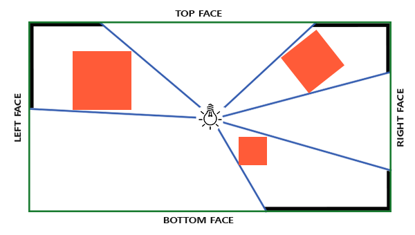
The depth map we need requires rendering a scene from all surrounding directions of a point light and as such a normal 2D depth map won't work; what if we were to use a cubemap instead? Because a cubemap can store full environment data with only 6 faces, it is possible to render the entire scene to each of the faces of a cubemap and sample these as the point light's surrounding depth values.
The generated depth cubemap is then passed to the lighting fragment shader that samples the cubemap with a direction vector to obtain the closest depth (from the light's perspective) at that fragment. Most of the complicated stuff we've already discussed in the shadow mapping chapter. What makes this technique a bit more difficult is the depth cubemap generation.
Generating the depth cubemap
To create a cubemap of a light's surrounding depth values we have to render the scene 6 times: once for each face. One (quite obvious) way to do this, is render the scene 6 times with 6 different view matrices, each time attaching a different cubemap face to the framebuffer object. This would look something like this:
for(unsigned int i = 0; i < 6; i++)
{
GLenum face = GL_TEXTURE_CUBE_MAP_POSITIVE_X + i;
glFramebufferTexture2D (GL_FRAMEBUFFER, GL_DEPTH_ATTACHMENT, face, depthCubemap, 0);
BindViewMatrix(lightViewMatrices[i]);
RenderScene();
}
This can be quite expensive though as a lot of render calls are necessary for this single depth map. In this chapter we're going to use an alternative (more organized) approach using a little trick in the geometry shader that allows us to build the depth cubemap with just a single render pass.
First, we'll need to create a cubemap:
unsigned int depthCubemap;
glGenTextures (1, &depthCubemap);
And assign each of the single cubemap faces a 2D depth-valued texture image:
const unsigned int SHADOW_WIDTH = 1024, SHADOW_HEIGHT = 1024;
glBindTexture (GL_TEXTURE_CUBE_MAP, depthCubemap);
for (unsigned int i = 0; i < 6; ++i)
glTexImage2D (GL_TEXTURE_CUBE_MAP_POSITIVE_X + i, 0, GL_DEPTH_COMPONENT,
SHADOW_WIDTH, SHADOW_HEIGHT, 0, GL_DEPTH_COMPONENT, GL_FLOAT, NULL);
And don't forget to set the texture parameters:
glTexParameter i(GL_TEXTURE_CUBE_MAP, GL_TEXTURE_MAG_FILTER, GL_NEAREST);
glTexParameter i(GL_TEXTURE_CUBE_MAP, GL_TEXTURE_MIN_FILTER, GL_NEAREST);
glTexParameter i(GL_TEXTURE_CUBE_MAP, GL_TEXTURE_WRAP_S, GL_CLAMP_TO_EDGE);
glTexParameter i(GL_TEXTURE_CUBE_MAP, GL_TEXTURE_WRAP_T, GL_CLAMP_TO_EDGE);
glTexParameter i(GL_TEXTURE_CUBE_MAP, GL_TEXTURE_WRAP_R, GL_CLAMP_TO_EDGE);
Normally we'd attach a single face of a cubemap texture to the framebuffer object and render the scene 6 times, each time switching the depth buffer target of the framebuffer to a different cubemap face. Since we're going to use a geometry shader, that allows us to render to all faces in a single pass, we can directly attach the cubemap as a framebuffer's depth attachment with
glBindFramebuffer (GL_FRAMEBUFFER, depthMapFBO);
glFramebufferTexture(GL_FRAMEBUFFER, GL_DEPTH_ATTACHMENT, depthCubemap, 0);
glDrawBuffer(GL_NONE);
glReadBuffer(GL_NONE);
glBindFramebuffer (GL_FRAMEBUFFER, 0);
Again, note the call to
With omnidirectional shadow maps we have two render passes: first, we generate the depth cubemap and second, we use the depth cubemap in the normal render pass to add shadows to the scene. This process looks a bit like this:
// 1. first render to depth cubemap
glViewport (0, 0, SHADOW_WIDTH, SHADOW_HEIGHT);
glBindFramebuffer (GL_FRAMEBUFFER, depthMapFBO);
glClear (GL_DEPTH_BUFFER_BIT);
ConfigureShaderAndMatrices();
RenderScene();
glBindFramebuffer (GL_FRAMEBUFFER, 0);
// 2. then render scene as normal with shadow mapping (using depth cubemap)
glViewport (0, 0, SCR_WIDTH, SCR_HEIGHT);
glClear (GL_COLOR_BUFFER_BIT | GL_DEPTH_BUFFER_BIT);
ConfigureShaderAndMatrices();
glBindTexture (GL_TEXTURE_CUBE_MAP, depthCubemap);
RenderScene();
The process is exactly the same as with default shadow mapping, although this time we render to and use a cubemap depth texture compared to a 2D depth texture.
Light space transform
With the framebuffer and cubemap set, we need some way to transform all the scene's geometry to the relevant light spaces in all 6 directions of the light. Just like the shadow mapping chapter we're going to need a light space transformation matrix \(T\), but this time one for each face.
Each light space transformation matrix contains both a projection and a view matrix. For the projection matrix we're going to use a perspective projection matrix; the light source represents a point in space so perspective projection makes most sense. Each light space transformation matrix uses the same projection matrix:
float aspect = (float)SHADOW_WIDTH/(float)SHADOW_HEIGHT;
float near = 1.0f;
float far = 25.0f;
glm::mat4 shadowProj = glm::perspective (glm::radians (90.0f), aspect, near, far);
Important to note here is the field of view parameter of
As the projection matrix does not change per direction we can re-use it for each of the 6 transformation matrices. We do need a different view matrix per direction. With
std::vector<glm::mat4> shadowTransforms;
shadowTransforms.push_back(shadowProj *
glm::lookAt (lightPos, lightPos + glm::vec3( 1.0, 0.0, 0.0), glm::vec3(0.0,-1.0, 0.0));
shadowTransforms.push_back(shadowProj *
glm::lookAt (lightPos, lightPos + glm::vec3(-1.0, 0.0, 0.0), glm::vec3(0.0,-1.0, 0.0));
shadowTransforms.push_back(shadowProj *
glm::lookAt (lightPos, lightPos + glm::vec3( 0.0, 1.0, 0.0), glm::vec3(0.0, 0.0, 1.0));
shadowTransforms.push_back(shadowProj *
glm::lookAt (lightPos, lightPos + glm::vec3( 0.0,-1.0, 0.0), glm::vec3(0.0, 0.0,-1.0));
shadowTransforms.push_back(shadowProj *
glm::lookAt (lightPos, lightPos + glm::vec3( 0.0, 0.0, 1.0), glm::vec3(0.0,-1.0, 0.0));
shadowTransforms.push_back(shadowProj *
glm::lookAt (lightPos, lightPos + glm::vec3( 0.0, 0.0,-1.0), glm::vec3(0.0,-1.0, 0.0));
Here we create 6 view matrices and multiply them with the projection matrix to get a total of 6 different light space transformation matrices. The target parameter of
These transformation matrices are sent to the shaders that render the depth into the cubemap.
Depth shaders
To render depth values to a depth cubemap we're going to need a total of three shaders: a vertex and fragment shader, and a geometry shader in between.
The geometry shader will be the shader responsible for transforming all world-space vertices to the 6 different light spaces. Therefore, the vertex shader simply transforms vertices to world-space and directs them to the geometry shader:
#version 330 core
layout (location = 0) in vec3 aPos;

uniform mat4 model;

void main()
{
    gl_Position = model * vec4(aPos, 1.0);
}
The geometry shader will take as input 3 triangle vertices and a uniform array of light space transformation matrices. The geometry shader is responsible for transforming the vertices to the light spaces; this is also where it gets interesting.
The geometry shader has a built-in variable called gl_Layer that specifies which cubemap face to emit a primitive to. When left alone, the geometry shader just sends its primitives further down the pipeline as usual, but when we update this variable we can control to which cubemap face we render to for each primitive. This of course only works when we have a cubemap texture attached to the active framebuffer.
#version 330 core
layout (triangles) in;
layout (triangle_strip, max_vertices=18) out;

uniform mat4 shadowMatrices[6];

out vec4 FragPos; // FragPos from GS (output per emitvertex)

void main()
{
    for(int face = 0; face < 6; ++face)
    {
        gl_Layer = face; // built-in variable that specifies to which face we render.
        for(int i = 0; i < 3; ++i) // for each triangle vertex
        {
            FragPos = gl_in[i].gl_Position;
            gl_Position = shadowMatrices[face] * FragPos;
            EmitVertex();
        }
        EndPrimitive();
    }
}
This geometry shader is relatively straightforward. We take as input a triangle, and output a total of 6 triangles (6 * 3 equals 18 vertices). In the
In the last chapter we used an empty fragment shader and let OpenGL figure out the depth values of the depth map. This time we're going to calculate our own (linear) depth as the linear distance between each closest fragment position and the light source's position. Calculating our own depth values makes the later shadow calculations a bit more intuitive.
#version 330 core
in vec4 FragPos;

uniform vec3 lightPos;
uniform float far_plane;

void main()
{
    // get distance between fragment and light source
    float lightDistance = length(FragPos.xyz - lightPos);

    // map to [0;1] range by dividing by far_plane
    lightDistance = lightDistance / far_plane;

    // write this as modified depth
    gl_FragDepth = lightDistance;
}
The fragment shader takes as input the FragPos from the geometry shader, the light's position vector, and the frustum's far plane value. Here we take the distance between the fragment and the light source, map it to the [0,1] range and write it as the fragment's depth value.
Rendering the scene with these shaders and the cubemap-attached framebuffer object active should give you a completely filled depth cubemap for the second pass's shadow calculations.
Omnidirectional shadow maps
With everything set up it is time to render the actual omnidirectional shadows. The procedure is similar to the directional shadow mapping chapter, although this time we bind a cubemap texture instead of a 2D texture and also pass the light projection's far plane variable to the shaders.
glViewport (0, 0, SCR_WIDTH, SCR_HEIGHT);
glClear (GL_COLOR_BUFFER_BIT | GL_DEPTH_BUFFER_BIT);
shader.use();
// ... send uniforms to shader (including light's far_plane value)
glActiveTexture (GL_TEXTURE0);
glBindTexture (GL_TEXTURE_CUBE_MAP, depthCubemap);
// ... bind other textures
RenderScene();
Here the
The vertex and fragment shader are mostly similar to the original shadow mapping shaders: the difference being that the fragment shader no longer requires a fragment position in light space as we can now sample the depth values with a direction vector.
Because of this, the vertex shader doesn't needs to transform its position vectors to light space so we can remove the FragPosLightSpace variable:
#version 330 core
layout (location = 0) in vec3 aPos;
layout (location = 1) in vec3 aNormal;
layout (location = 2) in vec2 aTexCoords;

out vec2 TexCoords;

out VS_OUT {
    vec3 FragPos;
    vec3 Normal;
    vec2 TexCoords;
} vs_out;

uniform mat4 projection;
uniform mat4 view;
uniform mat4 model;

void main()
{
    vs_out.FragPos = vec3(model * vec4(aPos, 1.0));
    vs_out.Normal = transpose(inverse(mat3(model))) * aNormal;
    vs_out.TexCoords = aTexCoords;
    gl_Position = projection * view * model * vec4(aPos, 1.0);
}
The fragment shader's Blinn-Phong lighting code is exactly the same as we had before with a shadow multiplication at the end:
#version 330 core
out vec4 FragColor;

in VS_OUT {
    vec3 FragPos;
    vec3 Normal;
    vec2 TexCoords;
} fs_in;

uniform sampler2D diffuseTexture;
uniform samplerCube depthMap;

uniform vec3 lightPos;
uniform vec3 viewPos;

uniform float far_plane;

float ShadowCalculation(vec3 fragPos)
{
    [...]
}

void main()
{
    vec3 color = texture(diffuseTexture, fs_in.TexCoords).rgb;
    vec3 normal = normalize(fs_in.Normal);
    vec3 lightColor = vec3(0.3);
    // ambient
    vec3 ambient = 0.3 * color;
    // diffuse
    vec3 lightDir = normalize(lightPos - fs_in.FragPos);
    float diff = max(dot(lightDir, normal), 0.0);
    vec3 diffuse = diff * lightColor;
    // specular
    vec3 viewDir = normalize(viewPos - fs_in.FragPos);
    vec3 reflectDir = reflect(-lightDir, normal);
    float spec = 0.0;
    vec3 halfwayDir = normalize(lightDir + viewDir);
    spec = pow(max(dot(normal, halfwayDir), 0.0), 64.0);
    vec3 specular = spec * lightColor;
    // calculate shadow
    float shadow = ShadowCalculation(fs_in.FragPos);
    vec3 lighting = (ambient + (1.0 - shadow) * (diffuse + specular)) * color;

    FragColor = vec4(lighting, 1.0);
}
There are a few subtle differences: the lighting code is the same, but we now have a samplerCube uniform and the
The biggest difference is in the content of the
The first thing we have to do is retrieve the depth of the cubemap. You may remember from the cubemap section of this chapter that we stored the depth as the linear distance between the fragment and the light position; we're taking a similar approach here:
float ShadowCalculation(vec3 fragPos)
{
    vec3 fragToLight = fragPos - lightPos;
    float closestDepth = texture(depthMap, fragToLight).r;
}
Here we take the difference vector between the fragment's position and the light's position and use that vector as a direction vector to sample the cubemap. The direction vector doesn't need to be a unit vector to sample from a cubemap so there's no need to normalize it. The resulting closestDepth value is the normalized depth value between the light source and its closest visible fragment.
The closestDepth value is currently in the range [0,1] so we first transform it back to [0,far_plane] by multiplying it with far_plane.
closestDepth *= far_plane;
Next we retrieve the depth value between the current fragment and the light source, which we can easily obtain by taking the length of fragToLight due to how we calculated depth values in the cubemap:
float currentDepth = length(fragToLight);
This returns a depth value in the same (or larger) range as closestDepth.
Now we can compare both depth values to see which is closer than the other and determine whether the current fragment is in shadow. We also include a shadow bias so we don't get shadow acne as discussed in the previous chapter.
float bias = 0.05;
float shadow = currentDepth -  bias > closestDepth ? 1.0 : 0.0;
The complete
float ShadowCalculation(vec3 fragPos)
{
    // get vector between fragment position and light position
    vec3 fragToLight = fragPos - lightPos;
    // use the light to fragment vector to sample from the depth map
    float closestDepth = texture(depthMap, fragToLight).r;
    // it is currently in linear range between [0,1]. Re-transform back to original value
    closestDepth *= far_plane;
    // now get current linear depth as the length between the fragment and light position
    float currentDepth = length(fragToLight);
    // now test for shadows
    float bias = 0.05;
    float shadow = currentDepth -  bias > closestDepth ? 1.0 : 0.0;

    return shadow;
}
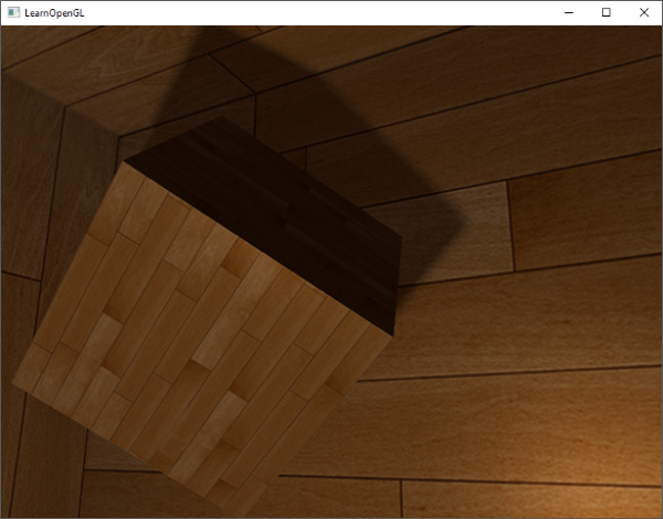
With these shaders we already get pretty good shadows and this time in all surrounding directions from a point light. With a point light positioned at the center of a simple scene it'll look a bit like this:
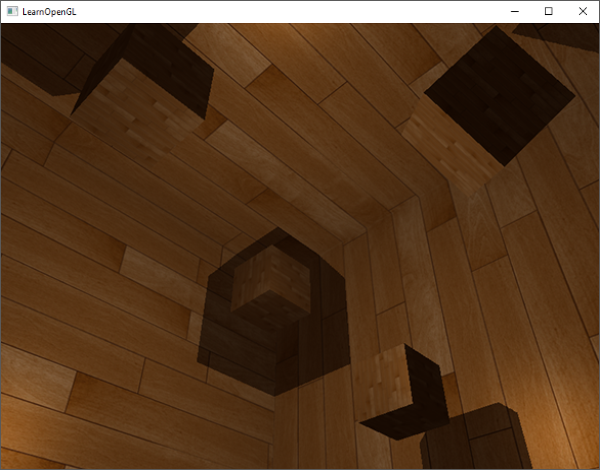
You can find the source code of this demo here.
Visualizing cubemap depth buffer
If you're somewhat like me you probably didn't get this right on the first try so it makes sense to do some debugging, with one of the obvious checks being validating whether the depth map was built correctly. A simple trick to visualize the depth buffer is to take the closestDepth variable in the
FragColor = vec4(vec3(closestDepth / far_plane), 1.0);
The result is a grayed out scene where each color represents the linear depth values of the scene:
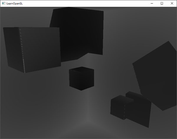
You can also see the to-be shadowed regions on the outside wall. If it looks somewhat similar, you know the depth cubemap was properly generated.
PCF
Since omnidirectional shadow maps are based on the same principles of traditional shadow mapping it also has the same resolution dependent artifacts. If you zoom in close enough you can again see jagged edges.
If we take the same simple PCF filter of the previous chapter and add a third dimension we get:
float shadow  = 0.0;
float bias    = 0.05;
float samples = 4.0;
float offset  = 0.1;
for(float x = -offset; x < offset; x += offset / (samples * 0.5))
{
    for(float y = -offset; y < offset; y += offset / (samples * 0.5))
    {
        for(float z = -offset; z < offset; z += offset / (samples * 0.5))
        {
            float closestDepth = texture(depthMap, fragToLight + vec3(x, y, z)).r;
            closestDepth *= far_plane;   // undo mapping [0;1]
            if(currentDepth - bias > closestDepth)
                shadow += 1.0;
        }
    }
}
shadow /= (samples * samples * samples);
The code isn't that different from the traditional shadow mapping code. We calculate and add texture offsets dynamically for each axis based on a fixed number of samples. For each sample we repeat the original shadow process on the offsetted sample direction and average the results at the end.
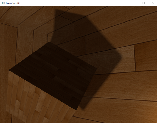
The shadows now look more soft and smooth and give more plausible results.
However, with samples set to 4.0 we take a total of 64 samples each fragment which is a lot!
As most of these samples are redundant in that they sample close to the original direction vector it may make more sense to only sample in perpendicular directions of the sample direction vector. However as there is no (easy) way to figure out which sub-directions are redundant this becomes difficult. One trick we can use is to take an array of offset directions that are all roughly separable e.g. each of them points in completely different directions. This will significantly reduce the number of sub-directions that are close together. Below we have such an array of a maximum of 20 offset directions:
vec3 sampleOffsetDirections[20] = vec3[]
(
   vec3( 1,  1,  1), vec3( 1, -1,  1), vec3(-1, -1,  1), vec3(-1,  1,  1),
   vec3( 1,  1, -1), vec3( 1, -1, -1), vec3(-1, -1, -1), vec3(-1,  1, -1),
   vec3( 1,  1,  0), vec3( 1, -1,  0), vec3(-1, -1,  0), vec3(-1,  1,  0),
   vec3( 1,  0,  1), vec3(-1,  0,  1), vec3( 1,  0, -1), vec3(-1,  0, -1),
   vec3( 0,  1,  1), vec3( 0, -1,  1), vec3( 0, -1, -1), vec3( 0,  1, -1)
);
From this we can adapt the PCF algorithm to take a fixed amount of samples from sampleOffsetDirections and use these to sample the cubemap. The advantage here is that we need a lot less samples to get visually similar results.
float shadow = 0.0;
float bias   = 0.15;
int samples  = 20;
float viewDistance = length(viewPos - fragPos);
float diskRadius = 0.05;
for(int i = 0; i < samples; ++i)
{
    float closestDepth = texture(depthMap, fragToLight + sampleOffsetDirections[i] * diskRadius).r;
    closestDepth *= far_plane;   // undo mapping [0;1]
    if(currentDepth - bias > closestDepth)
        shadow += 1.0;
}
shadow /= float(samples);
Here we add multiple offsets, scaled by some diskRadius, around the original fragToLight direction vector to sample from the cubemap.
Another interesting trick we can apply here is that we can change diskRadius based on the distance of the viewer to the fragment, making the shadows softer when far away and sharper when close by.
float diskRadius = (1.0 + (viewDistance / far_plane)) / 25.0;
The results of the updated PCF algorithm gives just as good, if not better, results of soft shadows:
Of course, the bias we add to each sample is highly based on context and will always require tweaking based on the scene you're working with. Play around with all the values and see how they affect the scene.
You can find the final code here: here.
I should mention that using geometry shaders to generate a depth map isn't necessarily faster than rendering the scene 6 times for each face. Using a geometry shader like this has its own performance penalties that may outweigh the performance gain of using one in the first place. This of course depends on the type of environment, the specific video card drivers, and plenty of other factors. So if you really care about pushing the most out of your system, make sure to profile both methods and select the more efficient one for your scene.
Additional resources
- Shadow Mapping for point light sources in OpenGL: omnidirectional shadow mapping tutorial by sunandblackcat.
- Multipass Shadow Mapping With Point Lights: omnidirectional shadow mapping tutorial by ogldev.
- Omni-directional Shadows: a nice set of slides about omnidirectional shadow mapping by Peter Houska.