


Basic Lighting
Lighting/Basic-Lighting
Lighting in the real world is extremely complicated and depends on way too many factors, something we can't afford to calculate on the limited processing power we have. Lighting in OpenGL is therefore based on approximations of reality using simplified models that are much easier to process and look relatively similar. These lighting models are based on the physics of light as we understand it. One of those models is called the
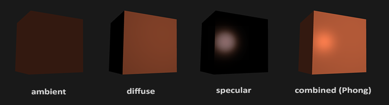
Ambient lighting : even when it is dark there is usually still some light somewhere in the world (the moon, a distant light) so objects are almost never completely dark. To simulate this we use an ambient lighting constant that always gives the object some color.Diffuse lighting : simulates the directional impact a light object has on an object. This is the most visually significant component of the lighting model. The more a part of an object faces the light source, the brighter it becomes.Specular lighting : simulates the bright spot of a light that appears on shiny objects. Specular highlights are more inclined to the color of the light than the color of the object.
To create visually interesting scenes we want to at least simulate these 3 lighting components. We'll start with the simplest one: ambient lighting.
Ambient lighting
Light usually does not come from a single light source, but from many light sources scattered all around us, even when they're not immediately visible. One of the properties of light is that it can scatter and bounce in many directions, reaching spots that aren't directly visible; light can thus reflect on other surfaces and have an indirect impact on the lighting of an object. Algorithms that take this into consideration are called
Since we're not big fans of complicated and expensive algorithms we'll start by using a very simplistic model of global illumination, namely
Adding ambient lighting to the scene is really easy. We take the light's color, multiply it with a small constant ambient factor, multiply this with the object's color, and use that as the fragment's color in the cube object's shader:
void main()
{
    float ambientStrength = 0.1;
    vec3 ambient = ambientStrength * lightColor;

    vec3 result = ambient * objectColor;
    FragColor = vec4(result, 1.0);
}
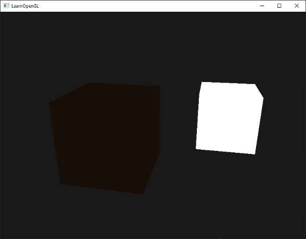
If you'd now run the program, you'll notice that the first stage of lighting is now successfully applied to the object. The object is quite dark, but not completely since ambient lighting is applied (note that the light cube is unaffected because we use a different shader). It should look something like this:
Diffuse lighting
Ambient lighting by itself doesn't produce the most interesting results, but diffuse lighting however will start to give a significant visual impact on the object. Diffuse lighting gives the object more brightness the closer its fragments are aligned to the light rays from a light source. To give you a better understanding of diffuse lighting take a look at the following image:

To the left we find a light source with a light ray targeted at a single fragment of our object. We need to measure at what angle the light ray touches the fragment. If the light ray is perpendicular to the object's surface the light has the greatest impact. To measure the angle between the light ray and the fragment we use something called a
You may remember from the transformations chapter that, the lower the angle between two unit vectors, the more the dot product is inclined towards a value of 1. When the angle between both vectors is 90 degrees, the dot product becomes 0. The same applies to \(\theta\): the larger \(\theta\) becomes, the less of an impact the light should have on the fragment's color.
1) so we need to make sure all the vectors are normalized, otherwise the dot product returns more than just the cosine (see Transformations).
The resulting dot product thus returns a scalar that we can use to calculate the light's impact on the fragment's color, resulting in differently lit fragments based on their orientation towards the light.
So, what do we need to calculate diffuse lighting:
- Normal vector: a vector that is perpendicular to the vertex' surface.
- The directed light ray: a direction vector that is the difference vector between the light's position and the fragment's position. To calculate this light ray we need the light's position vector and the fragment's position vector.
Normal vectors
A normal vector is a (unit) vector that is perpendicular to the surface of a vertex. Since a vertex by itself has no surface (it's just a single point in space) we retrieve a normal vector by using its surrounding vertices to figure out the surface of the vertex. We can use a little trick to calculate the normal vectors for all the cube's vertices by using the cross product, but since a 3D cube is not a complicated shape we can simply manually add them to the vertex data. The updated vertex data array can be found here. Try to visualize that the normals are indeed vectors perpendicular to each plane's surface (a cube consists of 6 planes).
Since we added extra data to the vertex array we should update the cube's vertex shader:
#version 330 core
layout (location = 0) in vec3 aPos;
layout (location = 1) in vec3 aNormal;
...
Now that we added a normal vector to each of the vertices and updated the vertex shader we should update the vertex attribute pointers as well. Note that the light source's cube uses the same vertex array for its vertex data, but the lamp shader has no use of the newly added normal vectors. We don't have to update the lamp's shaders or attribute configurations, but we have to at least modify the vertex attribute pointers to reflect the new vertex array's size:
glVertexAttribPointer (0, 3, GL_FLOAT, GL_FALSE, 6 * sizeof(float), (void*)0);
glEnable VertexAttribArray
We only want to use the first 3 floats of each vertex and ignore the last 3 floats so we only need to update the stride parameter to 6 times the size of a float and we're done.
All the lighting calculations are done in the fragment shader so we need to forward the normal vectors from the vertex shader to the fragment shader. Let's do that:
out vec3 Normal;

void main()
{
    gl_Position = projection * view * model * vec4(aPos, 1.0);
    Normal = aNormal;
}
What's left to do is declare the corresponding input variable in the fragment shader:
in vec3 Normal;
Calculating the diffuse color
We now have the normal vector for each vertex, but we still need the light's position vector and the fragment's position vector. Since the light's position is a single static variable we can declare it as a uniform in the fragment shader:
uniform vec3 lightPos;
And then update the uniform in the render loop (or outside since it doesn't change per frame). We use the lightPos vector declared in the previous chapter as the location of the diffuse light source:
lightingShader.setVec3("lightPos", lightPos);
Then the last thing we need is the actual fragment's position. We're going to do all the lighting calculations in world space so we want a vertex position that is in world space first. We can accomplish this by multiplying the vertex position attribute with the model matrix only (not the view and projection matrix) to transform it to world space coordinates. This can easily be accomplished in the vertex shader so let's declare an output variable and calculate its world space coordinates:
out vec3 FragPos;
out vec3 Normal;

void main()
{
    gl_Position = projection * view * model * vec4(aPos, 1.0);
    FragPos = vec3(model * vec4(aPos, 1.0));
    Normal = aNormal;
}
And lastly add the corresponding input variable to the fragment shader:
in vec3 FragPos;
This in variable will be interpolated from the 3 world position vectors of the triangle to form the FragPos vector that is the per-fragment world position. Now that all the required variables are set we can start the lighting calculations.
The first thing we need to calculate is the direction vector between the light source and the fragment's position. From the previous section we know that the light's direction vector is the difference vector between the light's position vector and the fragment's position vector. As you may remember from the transformations chapter we can easily calculate this difference by subtracting both vectors from each other. We also want to make sure all the relevant vectors end up as unit vectors so we normalize both the normal and the resulting direction vector:
vec3 norm = normalize(Normal);
vec3 lightDir = normalize(lightPos - FragPos);
Next we need to calculate the diffuse impact of the light on the current fragment by taking the dot product between the norm and lightDir vectors. The resulting value is then multiplied with the light's color to get the diffuse component, resulting in a darker diffuse component the greater the angle between both vectors:
float diff = max(dot(norm, lightDir), 0.0);
vec3 diffuse = diff * lightColor;
If the angle between both vectors is greater than 90 degrees then the result of the dot product will actually become negative and we end up with a negative diffuse component.
For that reason we use the
Now that we have both an ambient and a diffuse component we add both colors to each other and then multiply the result with the color of the object to get the resulting fragment's output color:
vec3 result = (ambient + diffuse) * objectColor;
FragColor = vec4(result, 1.0);
If your application (and shaders) compiled successfully you should see something like this:
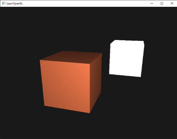
You can see that with diffuse lighting the cube starts to look like an actual cube again. Try visualizing the normal vectors in your head and move the camera around the cube to see that the larger the angle between the normal vector and the light's direction vector, the darker the fragment becomes.
Feel free to compare your source code with the complete source code here if you're stuck.
One last thing
in the previous section we passed the normal vector directly from the vertex shader to the fragment shader. However, the calculations in the fragment shader are all done in world space, so shouldn't we transform the normal vectors to world space coordinates as well? Basically yes, but it's not as simple as simply multiplying it with a model matrix.
First of all, normal vectors are only direction vectors and do not represent a specific position in space. Second, normal vectors do not have a homogeneous coordinate (the w component of a vertex position). This means that translations should not have any effect on the normal vectors. So if we want to multiply the normal vectors with a model matrix we want to remove the translation part of the matrix by taking the upper-left 3x3 matrix of the model matrix (note that we could also set the w component of a normal vector to 0 and multiply with the 4x4 matrix).
Second, if the model matrix would perform a non-uniform scale, the vertices would be changed in such a way that the normal vector is not perpendicular to the surface anymore. The following image shows the effect such a model matrix (with non-uniform scaling) has on a normal vector:
Whenever we apply a non-uniform scale (note: a uniform scale only changes the normal's magnitude, not its direction, which is easily fixed by normalizing it) the normal vectors are not perpendicular to the corresponding surface anymore which distorts the lighting.
The trick of fixing this behavior is to use a different model matrix specifically tailored for normal vectors. This matrix is called the
The normal matrix is defined as 'the transpose of the inverse of the upper-left 3x3 part of the model matrix'. Phew, that's a mouthful and if you don't really understand what that means, don't worry; we haven't discussed inverse and transpose matrices yet. Note that most resources define the normal matrix as derived from the model-view matrix, but since we're working in world space (and not in view space) we will derive it from the model matrix.
In the vertex shader we can generate the normal matrix by using the vec3 normal vector:
Normal = mat3(transpose(inverse(model))) * aNormal;
In the diffuse lighting section the lighting was fine because we didn't do any scaling on the object, so there was not really a need to use a normal matrix and we could've just multiplied the normals with the model matrix. If you are doing a non-uniform scale however, it is essential that you multiply your normal vectors with the normal matrix.
Specular Lighting
If you're not exhausted already by all the lighting talk we can start finishing the Phong lighting model by adding specular highlights.
Similar to diffuse lighting, specular lighting is based on the light's direction vector and the object's normal vectors, but this time it is also based on the view direction e.g. from what direction the player is looking at the fragment. Specular lighting is based on the reflective properties of surfaces. If we think of the object's surface as a mirror, the specular lighting is the strongest wherever we would see the light reflected on the surface. You can see this effect in the following image:
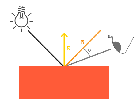
We calculate a reflection vector by reflecting the light direction around the normal vector. Then we calculate the angular distance between this reflection vector and the view direction. The closer the angle between them, the greater the impact of the specular light. The resulting effect is that we see a bit of a highlight when we're looking at the light's direction reflected via the surface.
The view vector is the one extra variable we need for specular lighting which we can calculate using the viewer's world space position and the fragment's position. Then we calculate the specular's intensity, multiply this with the light color and add this to the ambient and diffuse components.
(0,0,0) so you already got the position of the viewer for free. However, I find calculating lighting in world space more intuitive for learning purposes. If you still want to calculate lighting in view space you want to transform all the relevant vectors with the view matrix as well (don't forget to change the normal matrix too).
To get the world space coordinates of the viewer we simply take the position vector of the camera object (which is the viewer of course). So let's add another uniform to the fragment shader and pass the camera position vector to the shader:
uniform vec3 viewPos;
lightingShader.setVec3("viewPos", camera.Position);
Now that we have all the required variables we can calculate the specular intensity. First we define a specular intensity value to give the specular highlight a medium-bright color so that it doesn't have too much of an impact:
float specularStrength = 0.5;
If we would set this to 1.0f we'd get a really bright specular component which is a bit too much for a coral cube. In the next chapter we'll talk about properly setting all these lighting intensities and how they affect the objects. Next we calculate the view direction vector and the corresponding reflect vector along the normal axis:
vec3 viewDir = normalize(viewPos - FragPos);
vec3 reflectDir = reflect(-lightDir, norm);
Note that we negate the lightDir vector. The reflect function expects the first vector to point from the light source towards the fragment's position, but the lightDir vector is currently pointing the other way around: from the fragment towards the light source (this depends on the order of subtraction earlier on when we calculated the lightDir vector). To make sure we get the correct reflect vector we reverse its direction by negating the lightDir vector first. The second argument expects a normal vector so we supply the normalized norm vector.
Then what's left to do is to actually calculate the specular component. This is accomplished with the following formula:
float spec = pow(max(dot(viewDir, reflectDir), 0.0), 32);
vec3 specular = specularStrength * spec * lightColor;
We first calculate the dot product between the view direction and the reflect direction (and make sure it's not negative) and then raise it to the power of 32. This 32 value is the
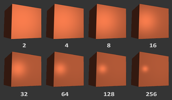
We don't want the specular component to be too distracting so we keep the exponent at 32. The only thing left to do is to add it to the ambient and diffuse components and multiply the combined result with the object's color:
vec3 result = (ambient + diffuse + specular) * objectColor;
FragColor = vec4(result, 1.0);
We now calculated all the lighting components of the Phong lighting model. Based on your point of view you should see something like this:
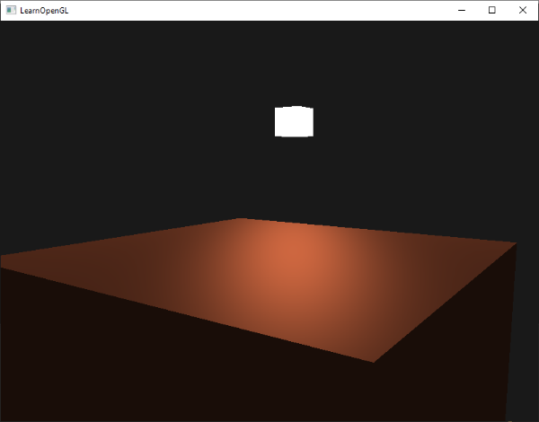
You can find the complete source code of the application here.
In the earlier days of lighting shaders, developers used to implement the Phong lighting model in the vertex shader. The advantage of doing lighting in the vertex shader is that it is a lot more efficient since there are generally a lot less vertices compared to fragments, so the (expensive) lighting calculations are done less frequently. However, the resulting color value in the vertex shader is the resulting lighting color of that vertex only and the color values of the surrounding fragments are then the result of interpolated lighting colors. The result was that the lighting was not very realistic unless large amounts of vertices were used:
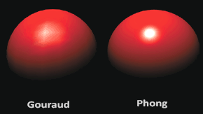
When the Phong lighting model is implemented in the vertex shader it is called
By now you should be starting to see just how powerful shaders are. With little information shaders are able to calculate how lighting affects the fragment's colors for all our objects. In the next chapters we'll be delving much deeper into what we can do with the lighting model.
Exercises
- Right now the light source is a boring static light source that doesn't move. Try to move the light source around the scene over time using either
sin orcos . Watching the lighting change over time gives you a good understanding of Phong's lighting model: solution. - Play around with different ambient, diffuse and specular strengths and see how they impact the result. Also experiment with the shininess factor. Try to comprehend why certain values have a certain visual output.
- Do Phong shading in view space instead of world space: solution.
- Implement Gouraud shading instead of Phong shading. If you did things right the lighting should look a bit off (especially the specular highlights) with the cube object. Try to reason why it looks so weird: solution.