


Geometry Shader
Advanced-OpenGL/Geometry-Shader
Between the vertex and the fragment shader there is an optional shader stage called the
We're going to throw you right into the deep by showing you an example of a geometry shader:
#version 330 core
layout (points) in;
layout (line_strip, max_vertices = 2) out;

void main() {
    gl_Position = gl_in[0].gl_Position + vec4(-0.1, 0.0, 0.0, 0.0);
    EmitVertex();

    gl_Position = gl_in[0].gl_Position + vec4( 0.1, 0.0, 0.0, 0.0);
    EmitVertex();

    EndPrimitive();
}
At the start of a geometry shader we need to declare the type of primitive input we're receiving from the vertex shader. We do this by declaring a layout specifier in front of the
points: when drawing GL_POINTS primitives (1).lines: when drawing GL_LINES or GL_LINE_STRIP (2).lines_adjacency: GL_LINES_ADJACENCY or GL_LINE_STRIP_ADJACENCY (4).triangles: GL_TRIANGLES, GL_TRIANGLE_STRIP or GL_TRIANGLE_FAN (3).triangles_adjacency: GL_TRIANGLES_ADJACENCY or GL_TRIANGLE_STRIP_ADJACENCY (6).
These are almost all the rendering primitives we're able to give to rendering calls like triangles. The number within the parenthesis represents the minimal number of vertices a single primitive contains.
We also need to specify a primitive type that the geometry shader will output and we do this via a layout specifier in front of the
pointsline_striptriangle_strip
With just these 3 output specifiers we can create almost any shape we want from the input primitives. To generate a single triangle for example we'd specify triangle_strip as the output and output 3 vertices.
The geometry shader also expects us to set a maximum number of vertices it outputs (if you exceed this number, OpenGL won't draw the extra vertices) which we can also do within the layout qualifier of the line_strip with a maximum number of 2 vertices.

To generate meaningful results we need some way to retrieve the output from the previous shader stage. GLSL gives us a
in gl_Vertex
{
    vec4  gl_Position;
    float gl_PointSize;
    float gl_ClipDistance[];
} gl_in[];
Here it is declared as an
Note that it is declared as an array, because most render primitives contain more than 1 vertex. The geometry shader receives all vertices of a primitive as its input.
Using the vertex data from the vertex shader stage we can generate new data with 2 geometry shader functions called
#version 330 core
layout (points) in;
layout (line_strip, max_vertices = 2) out;

void main() {
    gl_Position = gl_in[0].gl_Position + vec4(-0.1, 0.0, 0.0, 0.0);
    EmitVertex();

    gl_Position = gl_in[0].gl_Position + vec4( 0.1, 0.0, 0.0, 0.0);
    EmitVertex();

    EndPrimitive();
}
Each time we call
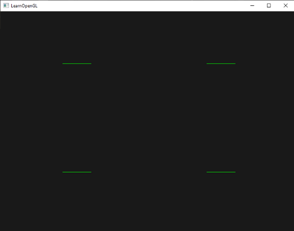
Now that you (sort of) know how geometry shaders work you can probably guess what this geometry shader does. This geometry shader takes a point primitive as its input and creates a horizontal line primitive with the input point at its center. If we were to render this it looks something like this:
Not very impressive yet, but it's interesting to consider that this output was generated using just the following render call:
glDrawArrays (GL_POINTS, 0, 4);
While this is a relatively simple example, it does show you how we can use geometry shaders to (dynamically) generate new shapes on the fly. Later in this chapter we'll discuss a few interesting effects that we can create using geometry shaders, but for now we're going to start with a simple example.
Using geometry shaders
To demonstrate the use of a geometry shader we're going to render a really simple scene where we draw 4 points on the z-plane in normalized device coordinates. The coordinates of the points are:
float points[] = {
	-0.5f,  0.5f, // top-left
	 0.5f,  0.5f, // top-right
	 0.5f, -0.5f, // bottom-right
	-0.5f, -0.5f  // bottom-left
};
The vertex shader needs to draw the points on the z-plane so we'll create a basic vertex shader:
#version 330 core
layout (location = 0) in vec2 aPos;

void main()
{
    gl_Position = vec4(aPos.x, aPos.y, 0.0, 1.0);
}
And we'll output the color green for all points which we code directly in the fragment shader:
#version 330 core
out vec4 FragColor;

void main()
{
    FragColor = vec4(0.0, 1.0, 0.0, 1.0);
}
Generate a VAO and a VBO for the points' vertex data and then draw them via
shader.use();
glBindVertexArray (VAO);
glDrawArrays (GL_POINTS, 0, 4);
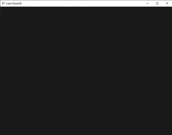
The result is a dark scene with 4 (difficult to see) green points:
But didn't we already learn to do all this? Yes, and now we're going to spice this little scene up by adding geometry shader magic to the scene.
For learning purposes we're first going to create what is called a
#version 330 core
layout (points) in;
layout (points, max_vertices = 1) out;

void main() {
    gl_Position = gl_in[0].gl_Position;
    EmitVertex();
    EndPrimitive();
}
By now this geometry shader should be fairly easy to understand. It simply emits the unmodified vertex position it received as input and generates a point primitive.
A geometry shader needs to be compiled and linked to a program just like the vertex and fragment shader, but this time we'll create the shader using GL_GEOMETRY_SHADER as the shader type:
geometryShader = glCreateShader (GL_GEOMETRY_SHADER);
glShaderSource (geometryShader, 1, &gShaderCode, NULL);
glCompileShader (geometryShader);
[...]
glAttachShader (program, geometryShader);
glLinkProgram (program);
The shader compilation code is the same as the vertex and fragment shaders. Be sure to check for compile or linking errors!
If you'd now compile and run you should be looking at a result that looks a bit like this:
It's exactly the same as without the geometry shader! It's a bit dull, I'll admit that, but the fact that we were still able to draw the points means that the geometry shader works, so now it's time for the more funky stuff!
Let's build houses
Drawing points and lines isn't that interesting so we're going to get a little creative by using the geometry shader to draw a house for us at the location of each point. We can accomplish this by setting the output of the geometry shader to
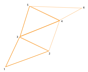
A triangle strip in OpenGL is a more efficient way to draw triangles with fewer vertices. After the first triangle is drawn, each subsequent vertex generates another triangle next to the first triangle: every 3 adjacent vertices will form a triangle. If we have a total of 6 vertices that form a triangle strip we'd get the following triangles: (1,2,3), (2,3,4), (3,4,5) and (4,5,6); forming a total of 4 triangles. A triangle strip needs at least 3 vertices and will generate N-2 triangles; with 6 vertices we created 6-2 = 4 triangles. The following image illustrates this:
Using a triangle strip as the output of the geometry shader we can easily create the house shape we're after by generating 3 adjacent triangles in the correct order. The following image shows in what order we need to draw what vertices to get the triangles we need with the blue dot being the input point:
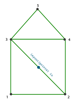
This translates to the following geometry shader:
#version 330 core
layout (points) in;
layout (triangle_strip, max_vertices = 5) out;

void build_house(vec4 position)
{
    gl_Position = position + vec4(-0.2, -0.2, 0.0, 0.0);    // 1:bottom-left
    EmitVertex();
    gl_Position = position + vec4( 0.2, -0.2, 0.0, 0.0);    // 2:bottom-right
    EmitVertex();
    gl_Position = position + vec4(-0.2,  0.2, 0.0, 0.0);    // 3:top-left
    EmitVertex();
    gl_Position = position + vec4( 0.2,  0.2, 0.0, 0.0);    // 4:top-right
    EmitVertex();
    gl_Position = position + vec4( 0.0,  0.4, 0.0, 0.0);    // 5:top
    EmitVertex();
    EndPrimitive();
}

void main() {
    build_house(gl_in[0].gl_Position);
}
This geometry shader generates 5 vertices, with each vertex being the point's position plus an offset to form one large triangle strip. The resulting primitive is then rasterized and the fragment shader runs on the entire triangle strip, resulting in a green house for each point we've rendered:
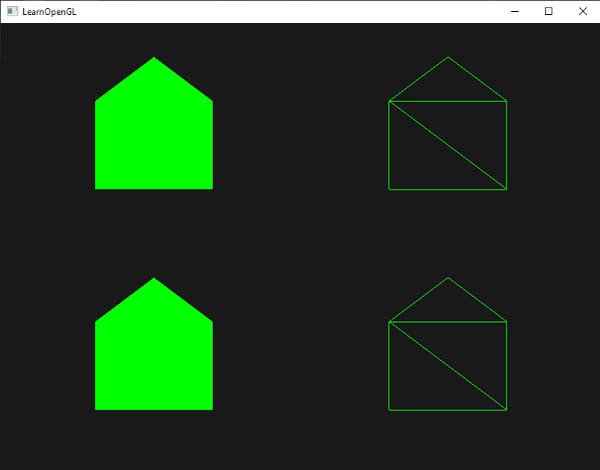
You can see that each house indeed consists of 3 triangles - all drawn using a single point in space. The green houses do look a bit boring though, so let's liven it up a bit by giving each house a unique color. To do this we're going to add an extra vertex attribute in the vertex shader with color information per vertex and direct it to the geometry shader that further forwards it to the fragment shader.
The updated vertex data is given below:
float points[] = {
    -0.5f,  0.5f, 1.0f, 0.0f, 0.0f, // top-left
     0.5f,  0.5f, 0.0f, 1.0f, 0.0f, // top-right
     0.5f, -0.5f, 0.0f, 0.0f, 1.0f, // bottom-right
    -0.5f, -0.5f, 1.0f, 1.0f, 0.0f  // bottom-left
};
Then we update the vertex shader to forward the color attribute to the geometry shader using an interface block:
#version 330 core
layout (location = 0) in vec2 aPos;
layout (location = 1) in vec3 aColor;

out VS_OUT {
    vec3 color;
} vs_out;

void main()
{
    gl_Position = vec4(aPos.x, aPos.y, 0.0, 1.0);
    vs_out.color = aColor;
}
Then we also need to declare the same interface block (with a different interface name) in the geometry shader:
in VS_OUT {
    vec3 color;
} gs_in[];
Because the geometry shader acts on a set of vertices as its input, its input data from the vertex shader is always represented as arrays of vertex data even though we only have a single vertex right now.
in vec3 outColor[];
out vec3 outColor. However, interface blocks are easier to work with in shaders like the geometry shader. In practice, geometry shader inputs can get quite large and grouping them in one large interface block array makes a lot more sense.
We should also declare an output color vector for the next fragment shader stage:
out vec3 fColor;
Because the fragment shader expects only a single (interpolated) color it doesn't make sense to forward multiple colors. The fColor vector is thus not an array, but a single vector. When emitting a vertex, that vertex will store the last stored value in fColor as that vertex's output value. For the houses, we can fill fColor once with the color from the vertex shader before the first vertex is emitted to color the entire house:
fColor = gs_in[0].color; // gs_in[0] since there's only one input vertex
gl_Position = position + vec4(-0.2, -0.2, 0.0, 0.0);    // 1:bottom-left
EmitVertex();
gl_Position = position + vec4( 0.2, -0.2, 0.0, 0.0);    // 2:bottom-right
EmitVertex();
gl_Position = position + vec4(-0.2,  0.2, 0.0, 0.0);    // 3:top-left
EmitVertex();
gl_Position = position + vec4( 0.2,  0.2, 0.0, 0.0);    // 4:top-right
EmitVertex();
gl_Position = position + vec4( 0.0,  0.4, 0.0, 0.0);    // 5:top
EmitVertex();
EndPrimitive();
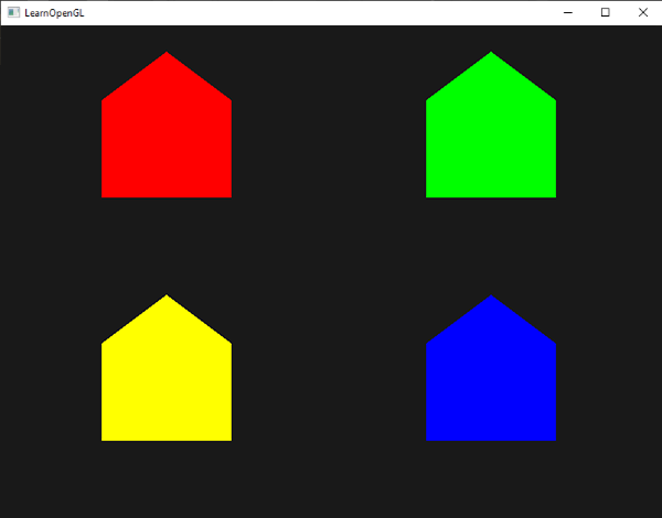
All the emitted vertices will have the last stored value in fColor embedded into their data, which is equal to the input vertex's color as we defined in its attributes. All the houses will now have a color of their own:
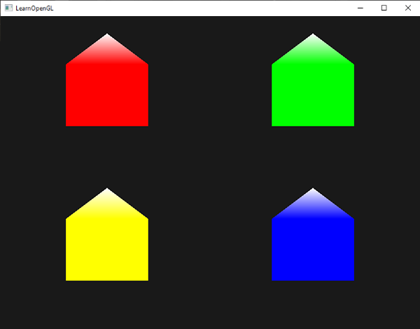
Just for fun we could also pretend it's winter and give their roofs a little snow by giving the last vertex a color of its own:
fColor = gs_in[0].color;
gl_Position = position + vec4(-0.2, -0.2, 0.0, 0.0);    // 1:bottom-left
EmitVertex();
gl_Position = position + vec4( 0.2, -0.2, 0.0, 0.0);    // 2:bottom-right
EmitVertex();
gl_Position = position + vec4(-0.2,  0.2, 0.0, 0.0);    // 3:top-left
EmitVertex();
gl_Position = position + vec4( 0.2,  0.2, 0.0, 0.0);    // 4:top-right
EmitVertex();
gl_Position = position + vec4( 0.0,  0.4, 0.0, 0.0);    // 5:top
fColor = vec3(1.0, 1.0, 1.0);
EmitVertex();
EndPrimitive();
The result now looks something like this:
You can compare your source code with the OpenGL code here.
You can see that with geometry shaders you can get pretty creative, even with the simplest primitives. Because the shapes are generated dynamically on the ultra-fast hardware of your GPU this can be a lot more powerful than defining these shapes yourself within vertex buffers. Geometry shaders are a great tool for simple (often-repeating) shapes, like cubes in a voxel world or grass leaves on a large outdoor field.
Exploding objects
While drawing houses is fun and all, it's not something we're going to use that much. That's why we're now going to take it up one notch and explode objects! That is something we're also probably not going to use that much either, but it's definitely fun to do!
When we say exploding an object we're not actually going to blow up our precious bundled sets of vertices, but we're going to move each triangle along the direction of their normal vector over a small period of time. The effect is that the entire object's triangles seem to explode. The effect of exploding triangles on the backpack model looks a bit like this:
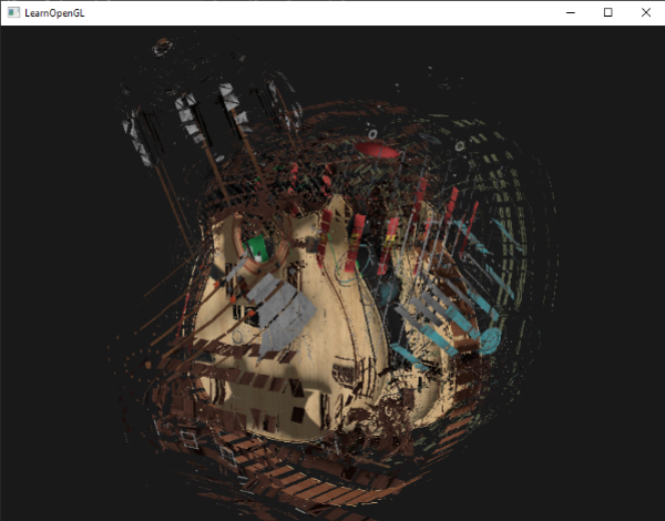
The great thing about such a geometry shader effect is that it works on all objects, regardless of their complexity.
Because we're going to translate each vertex into the direction of the triangle's normal vector we first need to calculate this normal vector. What we need to do is calculate a vector that is perpendicular to the surface of a triangle, using just the 3 vertices we have access to. You may remember from the transformations chapter that we can retrieve a vector perpendicular to two other vectors using the
vec3 GetNormal()
{
   vec3 a = vec3(gl_in[0].gl_Position) - vec3(gl_in[1].gl_Position);
   vec3 b = vec3(gl_in[2].gl_Position) - vec3(gl_in[1].gl_Position);
   return normalize(cross(a, b));
}
Here we retrieve two vectors a and b that are parallel to the surface of the triangle using vector subtraction. Subtracting two vectors from each other results in a vector that is the difference of the two vectors. Since all 3 points lie on the triangle plane, subtracting any of its vectors from each other results in a vector parallel to the plane. Do note that if we switched a and b in the
Now that we know how to calculate a normal vector we can create an
vec4 explode(vec4 position, vec3 normal)
{
    float magnitude = 2.0;
    vec3 direction = normal * ((sin(time) + 1.0) / 2.0) * magnitude;
    return position + vec4(direction, 0.0);
}
The function itself shouldn't be too complicated. The -1.0 and 1.0. Because we don't want to implode the object we transform the sin value to the [0,1] range. The resulting value is then used to scale the normal vector and the resulting direction vector is added to the position vector.
The complete geometry shader for the
#version 330 core
layout (triangles) in;
layout (triangle_strip, max_vertices = 3) out;

in VS_OUT {
    vec2 texCoords;
} gs_in[];

out vec2 TexCoords;

uniform float time;

vec4 explode(vec4 position, vec3 normal) { ... }

vec3 GetNormal() { ... }

void main() {
    vec3 normal = GetNormal();

    gl_Position = explode(gl_in[0].gl_Position, normal);
    TexCoords = gs_in[0].texCoords;
    EmitVertex();
    gl_Position = explode(gl_in[1].gl_Position, normal);
    TexCoords = gs_in[1].texCoords;
    EmitVertex();
    gl_Position = explode(gl_in[2].gl_Position, normal);
    TexCoords = gs_in[2].texCoords;
    EmitVertex();
    EndPrimitive();
}
Note that we're also outputting the appropriate texture coordinates before emitting a vertex.
Also don't forget to actually set the time uniform in your OpenGL code:
shader.setFloat("time", glfwGetTime ());
The result is a 3D model that seems to continually explode its vertices over time after which it returns to normal again. Although not exactly super useful, it does show you a more advanced use of the geometry shader. You can compare your source code with the complete source code here.
Visualizing normal vectors
To shake things up we're going to now discuss an example of using the geometry shader that is actually useful: visualizing the normal vectors of any object. When programming lighting shaders you will eventually run into weird visual outputs of which the cause is hard to determine. A common cause of lighting errors is incorrect normal vectors. Either caused by incorrectly loading vertex data, improperly specifying them as vertex attributes, or by incorrectly managing them in the shaders. What we want is some way to detect if the normal vectors we supplied are correct. A great way to determine if your normal vectors are correct is by visualizing them, and it just so happens that the geometry shader is an extremely useful tool for this purpose.
The idea is as follows: we first draw the scene as normal without a geometry shader and then we draw the scene a second time, but this time only displaying normal vectors that we generate via a geometry shader. The geometry shader takes as input a triangle primitive and generates 3 lines from them in the directions of their normal - one normal vector for each vertex. In code it'll look something like this:
shader.use();
DrawScene();
normalDisplayShader.use();
DrawScene();
This time we're creating a geometry shader that uses the vertex normals supplied by the model instead of generating it ourself. To accommodate for scaling and rotations (due to the view and model matrix) we'll transform the normals with a normal matrix. The geometry shader receives its position vectors as view-space coordinates so we should also transform the normal vectors to the same space. This can all be done in the vertex shader:
#version 330 core
layout (location = 0) in vec3 aPos;
layout (location = 1) in vec3 aNormal;

out VS_OUT {
    vec3 normal;
} vs_out;

uniform mat4 view;
uniform mat4 model;

void main()
{
    gl_Position = view * model * vec4(aPos, 1.0);
    mat3 normalMatrix = mat3(transpose(inverse(view * model)));
    vs_out.normal = normalize(vec3(vec4(normalMatrix * aNormal, 0.0)));
}
The transformed view-space normal vector is then passed to the next shader stage via an interface block. The geometry shader then takes each vertex (with a position and a normal vector) and draws a normal vector from each position vector:
#version 330 core
layout (triangles) in;
layout (line_strip, max_vertices = 6) out;

in VS_OUT {
    vec3 normal;
} gs_in[];

const float MAGNITUDE = 0.4;

uniform mat4 projection;

void GenerateLine(int index)
{
    gl_Position = projection * gl_in[index].gl_Position;
    EmitVertex();
    gl_Position = projection * (gl_in[index].gl_Position +
                                vec4(gs_in[index].normal, 0.0) * MAGNITUDE);
    EmitVertex();
    EndPrimitive();
}

void main()
{
    GenerateLine(0); // first vertex normal
    GenerateLine(1); // second vertex normal
    GenerateLine(2); // third vertex normal
}
The contents of geometry shaders like these should be self-explanatory by now. Note that we're multiplying the normal vector by a MAGNITUDE vector to restrain the size of the displayed normal vectors (otherwise they'd be a bit too large).
Since visualizing normals are mostly used for debugging purposes we can just display them as mono-colored lines (or super-fancy lines if you feel like it) with the help of the fragment shader:
#version 330 core
out vec4 FragColor;

void main()
{
    FragColor = vec4(1.0, 1.0, 0.0, 1.0);
}
Now rendering your model with normal shaders first and then with the special normal-visualizing shader you'll see something like this:
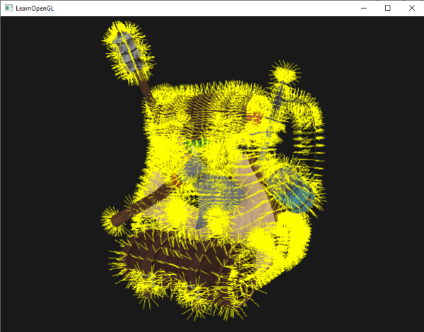
Apart from the fact that our backpack now looks a bit hairy, it gives us a really useful method for determining if the normal vectors of a model are indeed correct. You can imagine that geometry shaders like this could also be used for adding
You can find the OpenGL's source code here.