


Depth testing
Advanced-OpenGL/Depth-testing
In the coordinate systems chapter we've rendered a 3D container and made use of a
The depth-buffer is a buffer that, just like the 16, 24 or 32 bit floats. In most systems you'll see a depth buffer with a precision of 24 bits.
When depth testing is enabled, OpenGL tests the depth value of a fragment against the content of the depth buffer. OpenGL performs a depth test and if this test passes, the fragment is rendered and the depth buffer is updated with the new depth value. If the depth test fails, the fragment is discarded.
Depth testing is done in screen space after the fragment shader has run (and after the stencil test which we'll get to in the next chapter). The screen space coordinates relate directly to the viewport defined by OpenGL's
Fragment shaders are usually quite expensive so wherever we can avoid running them we should. A restriction on the fragment shader for early depth testing is that you shouldn't write to the fragment's depth value. If a fragment shader would write to its depth value, early depth testing is impossible; OpenGL won't be able to figure out the depth value beforehand.
Depth testing is disabled by default so to enable depth testing we need to enable it with the GL_DEPTH_TEST option:
glEnable (GL_DEPTH_TEST);
Once enabled, OpenGL automatically stores fragments their z-values in the depth buffer if they passed the depth test and discards fragments if they failed the depth test accordingly. If you have depth testing enabled you should also clear the depth buffer before each frame using GL_DEPTH_BUFFER_BIT; otherwise you're stuck with the depth values from last frame:
glClear (GL_COLOR_BUFFER_BIT | GL_DEPTH_BUFFER_BIT);
There are certain scenarios imaginable where you want to perform the depth test on all fragments and discard them accordingly, but not update the depth buffer. Basically, you're (temporarily) using a GL_FALSE:
glDepthMask (GL_FALSE);
Note that this only has effect if depth testing is enabled.
Depth test function
OpenGL allows us to modify the comparison operators it uses for the depth test. This allows us to control when OpenGL should pass or discard fragments and when to update the depth buffer. We can set the comparison operator (or depth function) by calling
glDepthFunc (GL_LESS);
The function accepts several comparison operators that are listed in the table below:
| Function | Description |
|---|---|
GL_ALWAYS |
The depth test always passes. |
GL_NEVER |
The depth test never passes. |
GL_LESS |
Passes if the fragment's depth value is less than the stored depth value. |
GL_EQUAL |
Passes if the fragment's depth value is equal to the stored depth value. |
GL_LEQUAL |
Passes if the fragment's depth value is less than or equal to the stored depth value. |
GL_GREATER |
Passes if the fragment's depth value is greater than the stored depth value. |
GL_NOTEQUAL |
Passes if the fragment's depth value is not equal to the stored depth value. |
GL_GEQUAL |
Passes if the fragment's depth value is greater than or equal to the stored depth value. |
By default the depth function GL_LESS is used that discards all the fragments that have a depth value higher than or equal to the current depth buffer's value.
Let's show the effect that changing the depth function has on the visual output. We'll use a fresh code setup that displays a basic scene with two textured cubes sitting on a textured floor with no lighting. You can find the source code here.
Within the source code we changed the depth function to GL_ALWAYS:
glEnable (GL_DEPTH_TEST);
glDepthFunc (GL_ALWAYS);
This simulates the same behavior we'd get if we didn't enable depth testing. The depth test always passes so the fragments that are drawn last are rendered in front of the fragments that were drawn before, even though they should've been at the front. Since we've drawn the floor plane last, the plane's fragments overwrite each of the container's previously written fragments:
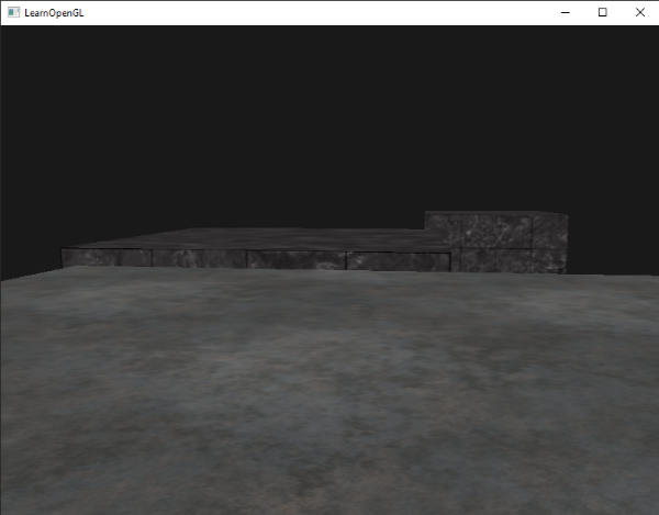
Setting it all back to GL_LESS gives us the type of scene we're used to:
Depth value precision
The depth buffer contains depth values between 0.0 and 1.0 and it compares its content with the z-values of all the objects in the scene as seen from the viewer. These z-values in view space can be any value between the projection-frustum's near and far plane. We thus need some way to transform these view-space z-values to the range of [0,1] and one way is to linearly transform them. The following (linear) equation transforms the z-value to a depth value between 0.0 and 1.0:
Here \(near\) and \(far\) are the near and far values we used to provide to the projection matrix to set the visible frustum (see coordinate Systems). The equation takes a depth value \(z\) within the frustum and transforms it to the range [0,1]. The relation between the z-value and its corresponding depth value is presented in the following graph:
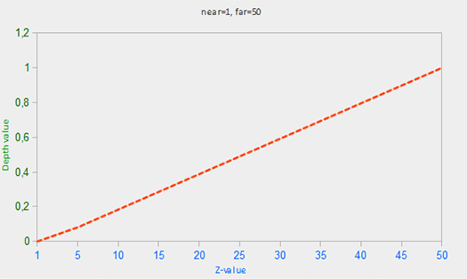
0.0 when the object is close by and a depth value close to 1.0 when the object is close to the far plane.
In practice however, a
Since the non-linear function is proportional to 1/z, z-values between 1.0 and 2.0 would result in depth values between 1.0 and 0.5 which is half of the [0,1] range, giving us enormous precision at small z-values. Z-values between 50.0 and 100.0 would account for only 2% of the [0,1] range. Such an equation, that also takes near and far distances into account, is given below:
Don't worry if you don't know exactly what is going on with this equation. The important thing to remember is that the values in the depth buffer are not linear in clip-space (they are linear in view-space before the projection matrix is applied). A value of 0.5 in the depth buffer does not mean the pixel's z-value is halfway in the frustum; the z-value of the vertex is actually quite close to the near plane! You can see the non-linear relation between the z-value and the resulting depth buffer's value in the following graph:
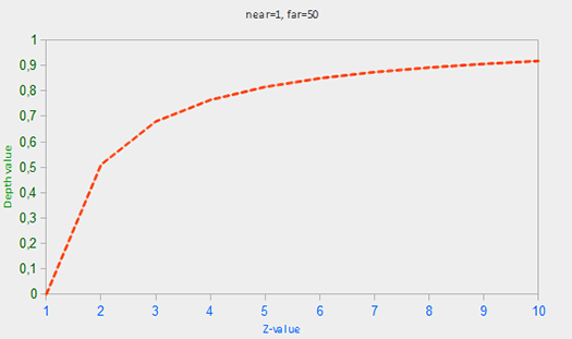
As you can see, the depth values are greatly determined by the small z-values giving us large depth precision to the objects close by. The equation to transform z-values (from the viewer's perspective) is embedded within the projection matrix so when we transform vertex coordinates from view to clip, and then to screen-space the non-linear equation is applied.
The effect of this non-linear equation quickly becomes apparent when we try to visualize the depth buffer.
Visualizing the depth buffer
We know that the z-value of the built-in gl_FragCoord vector in the fragment shader contains the depth value of that particular fragment. If we were to output this depth value of the fragment as a color we could display the depth values of all the fragments in the scene:
void main()
{
    FragColor = vec4(vec3(gl_FragCoord.z), 1.0);
}
If you'd then run the program you'll probably notice that everything is white, making it look like all of our depth values are the maximum depth value of 1.0. So why aren't any of the depth values closer to 0.0 and thus darker?
In the previous section we described that depth values in screen space are non-linear e.g. they have a very high precision for small z-values and a low precision for large z-values. The depth value of the fragment increases rapidly over distance so almost all the vertices have values close to 1.0. If we were to carefully move really close to an object you may eventually see the colors getting darker, their z-values becoming smaller:
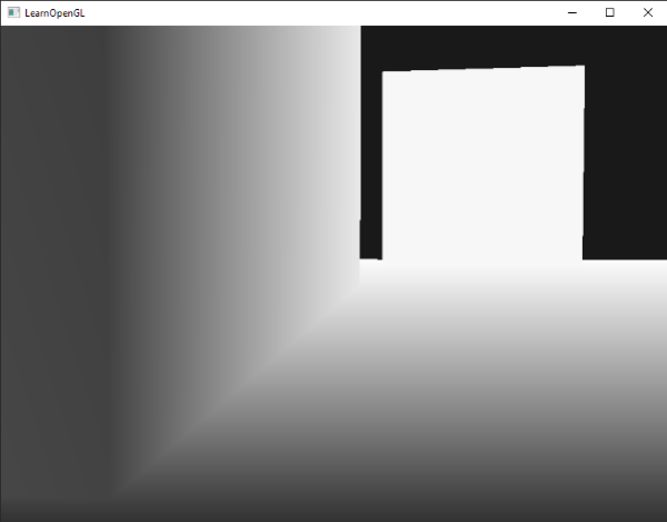
This clearly shows the non-linearity of the depth value. Objects close by have a much larger effect on the depth value than objects far away. Only moving a few inches can result in the colors going from dark to completely white.
We can however, transform the non-linear depth values of the fragment back to its linear sibling. To achieve this we basically need to reverse the process of projection for the depth values alone. This means we have to first re-transform the depth values from the range [0,1] to normalized device coordinates in the range [-1,1]. Then we want to reverse the non-linear equation (equation 2) as done in the projection matrix and apply this inversed equation to the resulting depth value. The result is then a linear depth value.
First we transform the depth value to NDC which is not too difficult:
float ndc = depth * 2.0 - 1.0;
We then take the resulting ndc value and apply the inverse transformation to retrieve its linear depth value:
float linearDepth = (2.0 * near * far) / (far + near - ndc * (far - near));
This equation is derived from the projection matrix for non-linearizing the depth values, returning depth values between near and far. This math-heavy article explains the projection matrix in enormous detail for the interested reader; it also shows where the equations come from.
The complete fragment shader that transforms the non-linear depth in screen-space to a linear depth value is then as follows:
#version 330 core
out vec4 FragColor;

float near = 0.1;
float far  = 100.0;

float LinearizeDepth(float depth)
{
    float z = depth * 2.0 - 1.0; // back to NDC
    return (2.0 * near * far) / (far + near - z * (far - near));
}

void main()
{
    float depth = LinearizeDepth(gl_FragCoord.z) / far; // divide by far for demonstration
    FragColor = vec4(vec3(depth), 1.0);
}
Because the linearized depth values range from near to far most of its values will be above 1.0 and displayed as completely white. By dividing the linear depth value by far in the 0, 1]. This way we can gradually see the scene become brighter the closer the fragments are to the projection frustum's far plane, which works better for visualization purposes.
If we'd now run the application we get depth values that are linear over distance. Try moving around the scene to see the depth values change in a linear fashion.
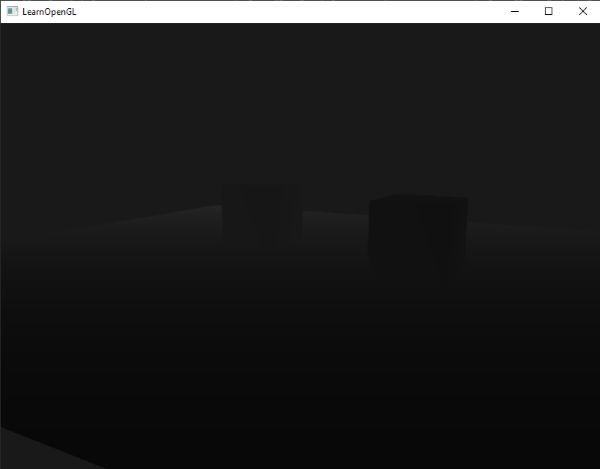
The colors are mostly black because the depth values range linearly from the near plane (0.1) to the far plane (100) which is still quite far away from us. The result is that we're relatively close to the near plane and therefore get lower (darker) depth values.
Z-fighting
A common visual artifact may occur when two planes or triangles are so closely aligned to each other that the depth buffer does not have enough precision to figure out which one of the two shapes is in front of the other. The result is that the two shapes continually seem to switch order which causes weird glitchy patterns. This is called
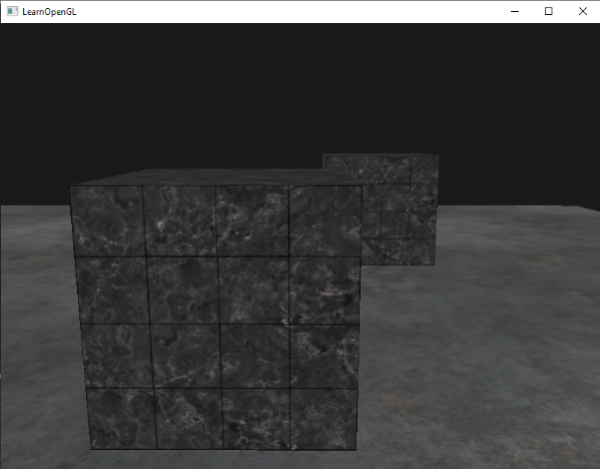
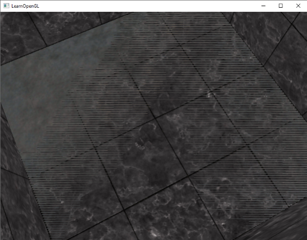
In the scene we've been using so far there are a few spots where z-fighting can be noticed. The containers were placed at the exact height of the floor which means the bottom plane of the container is coplanar with the floor plane. The depth values of both planes are then the same so the resulting depth test has no way of figuring out which is the right one.
If you move the camera inside one of the containers the effects are clearly visible, the bottom part of the container is constantly switching between the container's plane and the floor's plane in a zigzag pattern:
Z-fighting is a common problem with depth buffers and it's generally more noticeable when objects are further away (because the depth buffer has less precision at larger z-values). Z-fighting can't be completely prevented, but there are a few tricks that will help to mitigate or completely prevent z-fighting in your scene.
Prevent z-fighting
The first and most important trick is never place objects too close to each other in a way that some of their triangles closely overlap. By creating a small offset between two objects you can completely remove z-fighting between the two objects. In the case of the containers and the plane we could've easily moved the containers slightly upwards in the positive y direction. The small change of the container's positions would probably not be noticeable at all and would completely reduce the z-fighting. However, this requires manual intervention of each of the objects and thorough testing to make sure no objects in a scene produce z-fighting.
A second trick is to set the near plane as far as possible. In one of the previous sections we've discussed that precision is extremely large when close to the near plane so if we move the near plane away from the viewer, we'll have significantly greater precision over the entire frustum range. However, setting the near plane too far could cause clipping of near objects so it is usually a matter of tweaking and experimentation to figure out the best near distance for your scene.
Another great trick at the cost of some performance is to use a higher precision depth buffer. Most depth buffers have a precision of 24 bits, but most GPUs nowadays support 32 bit depth buffers, increasing the precision by a significant amount. So at the cost of some performance you'll get much more precision with depth testing, reducing z-fighting.
The 3 techniques we've discussed are the most common and easy-to-implement anti z-fighting techniques. There are some other techniques out there that require a lot more work and still won't completely disable z-fighting. Z-fighting is a common issue, but if you use the proper combination of the listed techniques you probably won't need to deal with z-fighting that much.