


Blending
Advanced-OpenGL/Blending
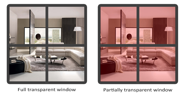
Transparent objects can be completely transparent (letting all colors through) or partially transparent (letting colors through, but also some of its own colors). The amount of transparency of an object is defined by its color's 1.0 giving the object 0.0 transparency. An alpha value of 0.0 would result in the object having complete transparency. An alpha value of 0.5 tells us the object's color consist of 50% of its own color and 50% of the colors behind the object.
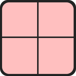
The textures we've used so far all consisted of 3 color components: red, green and blue, but some textures also have an embedded alpha channel that contains an 0.25 at its glass part and an alpha value of 0.0 at its corners. The glass part would normally be completely red, but since it has 75% transparency it largely shows the page's background through it, making it seem a lot less red:
We'll soon be adding this windowed texture to the scene from the depth testing chapter, but first we'll discuss an easier technique to implement transparency for pixels that are either fully transparent or fully opaque.
Discarding fragments
Some effects do not care about partial transparency, but either want to show something or nothing at all based on the color value of a texture. Think of grass; to create something like grass with little effort you generally paste a grass texture onto a 2D quad and place that quad into your scene. However, grass isn't exactly shaped like a 2D square so you only want to display some parts of the grass texture and ignore the others.
The following texture is exactly such a texture where it either is full opaque (an alpha value of 1.0) or it is fully transparent (an alpha value of 0.0) and nothing in between. You can see that wherever there is no grass, the image shows the page's background color instead of its own.
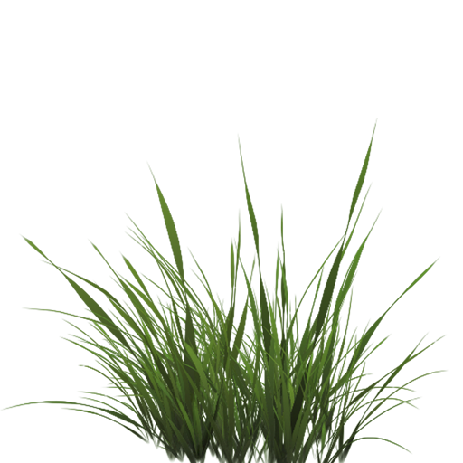
So when adding vegetation to a scene we don't want to see a square image of grass, but rather only show the actual grass and see through the rest of the image. We want to
Before we get into that we first need to learn how to load a transparent texture. To load textures with alpha values there's not much we need to change. stb_image automatically loads an image's alpha channel if it's available, but we do need to tell OpenGL our texture now uses an alpha channel in the texture generation procedure:
glTexImage2D (GL_TEXTURE_2D, 0, GL_RGBA, width, height, 0, GL_RGBA, GL_UNSIGNED_BYTE, data);
Also make sure that you retrieve all 4 color components of the texture in the fragment shader, not just the RGB components:
void main()
{
    // FragColor = vec4(vec3(texture(texture1, TexCoords)), 1.0);
    FragColor = texture(texture1, TexCoords);
}
Now that we know how to load transparent textures it's time to put it to the test by adding several of these leaves of grass throughout the basic scene introduced in the depth testing chapter.
We create a small vector array where we add several glm::vec3 vectors to represent the location of the grass leaves:
vector<glm::vec3> vegetation;
vegetation.push_back(glm::vec3(-1.5f,  0.0f, -0.48f));
vegetation.push_back(glm::vec3( 1.5f,  0.0f,  0.51f));
vegetation.push_back(glm::vec3( 0.0f,  0.0f,  0.7f));
vegetation.push_back(glm::vec3(-0.3f,  0.0f, -2.3f));
vegetation.push_back(glm::vec3( 0.5f,  0.0f, -0.6f));
Each of the grass objects is rendered as a single quad with the grass texture attached to it. It's not a perfect 3D representation of grass, but it's a lot more efficient than loading and rendering a large number of complex models. With a few tricks like adding randomized rotations and scales you can get pretty convincing results with quads.
Because the grass texture is going to be displayed on a quad object we'll need to create another VAO again, fill the VBO, and set the appropriate vertex attribute pointers. Then after we've rendered the floor and the two cubes we're going to render the grass leaves:
glBindVertexArray (vegetationVAO);
glBindTexture (GL_TEXTURE_2D, grassTexture);
for(unsigned int i = 0; i < vegetation.size(); i++)
{
model = glm::mat4(1.0f);
model = glm::translate (model, vegetation[i]);
shader.setMat4("model", model);
glDrawArrays (GL_TRIANGLES, 0, 6);
}
Running the application will now look a bit like this:
This happens because OpenGL by default does not know what to do with alpha values, nor when to discard them. We have to manually do this ourselves. Luckily this is quite easy thanks to the use of shaders. GLSL gives us the discard command that (once called) ensures the fragment will not be further processed and thus not end up into the color buffer. Thanks to this command we can check whether a fragment has an alpha value below a certain threshold and if so, discard the fragment as if it had never been processed:
#version 330 core
out vec4 FragColor;

in vec2 TexCoords;

uniform sampler2D texture1;

void main()
{
    vec4 texColor = texture(texture1, TexCoords);
    if(texColor.a < 0.1)
        discard;
    FragColor = texColor;
}
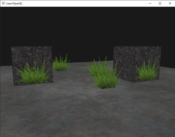
Here we check if the sampled texture color contains an alpha value lower than a threshold of 0.1 and if so, discard the fragment. This fragment shader ensures us that it only renders fragments that are not (almost) completely transparent. Now it'll look like it should:
glTexParameter i( GL_TEXTURE_2D, GL_TEXTURE_WRAP_S, GL_CLAMP_TO_EDGE);
glTexParameter i( GL_TEXTURE_2D, GL_TEXTURE_WRAP_T, GL_CLAMP_TO_EDGE);
You can find the source code here.
Blending
While discarding fragments is great and all, it doesn't give us the flexibility to render semi-transparent images; we either render the fragment or completely discard it. To render images with different levels of transparency we have to enable
glEnable (GL_BLEND);
Now that we've enabled blending we need to tell OpenGL how it should actually blend.
Blending in OpenGL happens with the following equation:
\begin{equation}\bar{C}_{result} = \bar{\color{green}C}_{source} * \color{green}F_{source} + \bar{\color{red}C}_{destination} * \color{red}F_{destination}\end{equation}- \(\bar{\color{green}C}_{source}\): the source color vector. This is the color output of the fragment shader.
- \(\bar{\color{red}C}_{destination}\): the destination color vector. This is the color vector that is currently stored in the color buffer.
- \(\color{green}F_{source}\): the source factor value. Sets the impact of the alpha value on the source color.
- \(\color{red}F_{destination}\): the destination factor value. Sets the impact of the alpha value on the destination color.
After the fragment shader has run and all the tests have passed, this
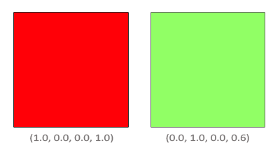
We have two squares where we want to draw the semi-transparent green square on top of the red square. The red square will be the destination color (and thus should be first in the color buffer) and we are now going to draw the green square over the red square.
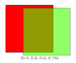
The question then arises: what do we set the factor values to? Well, we at least want to multiply the green square with its alpha value so we want to set the \(F_{src}\) equal to the alpha value of the source color vector which is 0.6. Then it makes sense to let the destination square have a contribution equal to the remainder of the alpha value. If the green square contributes 60% to the final color we want the red square to contribute 40% of the final color e.g. 1.0 - 0.6. So we set \(F_{destination}\) equal to one minus the alpha value of the source color vector. The equation thus becomes:
The result is that the combined square fragments contain a color that is 60% green and 40% red:
The resulting color is then stored in the color buffer, replacing the previous color.
So this is great and all, but how do we actually tell OpenGL to use factors like that? Well it just so happens that there is a function for this called
The
| Option | Value |
|---|---|
GL_ZERO |
Factor is equal to \(0\). |
GL_ONE |
Factor is equal to \(1\). |
GL_SRC_COLOR |
Factor is equal to the source color vector \(\bar{\color{green}C}_{source}\). |
GL_ONE_MINUS_SRC_COLOR |
Factor is equal to \(1\) minus the source color vector: \(1 - \bar{\color{green}C}_{source}\). |
GL_DST_COLOR |
Factor is equal to the destination color vector \(\bar{\color{red}C}_{destination}\) |
GL_ONE_MINUS_DST_COLOR |
Factor is equal to \(1\) minus the destination color vector: \(1 - \bar{\color{red}C}_{destination}\). |
GL_SRC_ALPHA |
Factor is equal to the \(alpha\) component of the source color vector \(\bar{\color{green}C}_{source}\). |
GL_ONE_MINUS_SRC_ALPHA |
Factor is equal to \(1 - alpha\) of the source color vector \(\bar{\color{green}C}_{source}\). |
GL_DST_ALPHA |
Factor is equal to the \(alpha\) component of the destination color vector \(\bar{\color{red}C}_{destination}\). |
GL_ONE_MINUS_DST_ALPHA |
Factor is equal to \(1 - alpha\) of the destination color vector \(\bar{\color{red}C}_{destination}\). |
GL_CONSTANT_COLOR |
Factor is equal to the constant color vector \(\bar{\color{blue}C}_{constant}\). |
GL_ONE_MINUS_CONSTANT_COLOR |
Factor is equal to \(1\) - the constant color vector \(\bar{\color{blue}C}_{constant}\). |
GL_CONSTANT_ALPHA |
Factor is equal to the \(alpha\) component of the constant color vector \(\bar{\color{blue}C}_{constant}\). |
GL_ONE_MINUS_CONSTANT_ALPHA |
Factor is equal to \(1 - alpha\) of the constant color vector \(\bar{\color{blue}C}_{constant}\). |
To get the blending result of our little two square example, we want to take the \(alpha\) of the source color vector for the source factor and \(1 - alpha\) of the same color vector for the destination factor. This translates to
glBlendFunc (GL_SRC_ALPHA, GL_ONE_MINUS_SRC_ALPHA);
It is also possible to set different options for the RGB and alpha channel individually using
glBlendFunc SeparateThis function sets the RGB components as we've set them previously, but only lets the resulting alpha component be influenced by the source's alpha value.
OpenGL gives us even more flexibility by allowing us to change the operator between the source and destination part of the equation. Right now, the source and destination components are added together, but we could also subtract them if we want.
GL_FUNC_ADD: the default, adds both colors to each other: \(\bar{C}_{result} = \color{green}{Src} + \color{red}{Dst}\).GL_FUNC_SUBTRACT: subtracts both colors from each other: \(\bar{C}_{result} = \color{green}{Src} - \color{red}{Dst}\).GL_FUNC_REVERSE_SUBTRACT: subtracts both colors, but reverses order: \(\bar{C}_{result} = \color{red}{Dst} - \color{green}{Src}\).GL_MIN: takes the component-wise minimum of both colors: \(\bar{C}_{result} = min(\color{red}{Dst}, \color{green}{Src})\).GL_MAX: takes the component-wise maximum of both colors: \(\bar{C}_{result} = max(\color{red}{Dst}, \color{green}{Src})\).
Usually we can simply omit a call to
Rendering semi-transparent textures
Now that we know how OpenGL works with regards to blending it's time to put our knowledge to the test by adding several semi-transparent windows. We'll be using the same scene as in the start of this chapter, but instead of rendering a grass texture we're now going to use the transparent window texture from the start of this chapter.
First, during initialization we enable blending and set the appropriate blending function:
glEnable (GL_BLEND);
glBlendFunc (GL_SRC_ALPHA, GL_ONE_MINUS_SRC_ALPHA);
Since we enabled blending there is no need to discard fragments so we'll reset the fragment shader to its original version:
#version 330 core
out vec4 FragColor;

in vec2 TexCoords;

uniform sampler2D texture1;

void main()
{
    FragColor = texture(texture1, TexCoords);
}
This time (whenever OpenGL renders a fragment) it combines the current fragment's color with the fragment color currently in the color buffer based on the alpha value of FragColor. Since the glass part of the window texture is semi-transparent we should be able to see the rest of the scene by looking through this window.
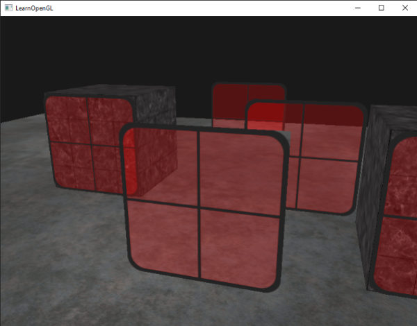
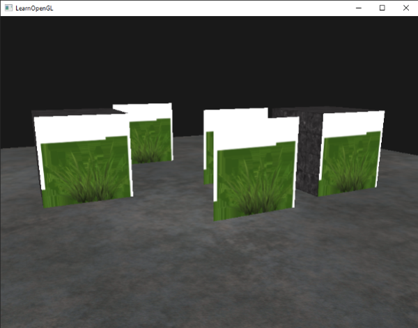
If you take a closer look however, you may notice something is off. The transparent parts of the front window are occluding the windows in the background. Why is this happening?
The reason for this is that depth testing works a bit tricky combined with blending. When writing to the depth buffer, the depth test does not care if the fragment has transparency or not, so the transparent parts are written to the depth buffer as any other value. The result is that the background windows are tested on depth as any other opaque object would be, ignoring transparency. Even though the transparent part should show the windows behind it, the depth test discards them.
So we cannot simply render the windows however we want and expect the depth buffer to solve all our issues for us; this is also where blending gets a little nasty. To make sure the windows show the windows behind them, we have to draw the windows in the background first. This means we have to manually sort the windows from furthest to nearest and draw them accordingly ourselves.
Don't break the order
To make blending work for multiple objects we have to draw the most distant object first and the closest object last. The normal non-blended objects can still be drawn as normal using the depth buffer so they don't have to be sorted. We do have to make sure they are drawn first before drawing the (sorted) transparent objects. When drawing a scene with non-transparent and transparent objects the general outline is usually as follows:
- Draw all opaque objects first.
- Sort all the transparent objects.
- Draw all the transparent objects in sorted order.
One way of sorting the transparent objects is to retrieve the distance of an object from the viewer's perspective. This can be achieved by taking the distance between the camera's position vector and the object's position vector. We then store this distance together with the corresponding position vector in a
std::map<float, glm::vec3> sorted;
for (unsigned int i = 0; i < windows.size(); i++)
{
    float distance = glm::length(camera.Position - windows[i]);
    sorted[distance] = windows[i];
}
The result is a sorted container object that stores each of the window positions based on their distance key value from lowest to highest distance.
Then, this time when rendering, we take each of the map's values in reverse order (from farthest to nearest) and then draw the corresponding windows in correct order:
for(std::map<float,glm::vec3>::reverse_iterator it = sorted.rbegin(); it != sorted.rend(); ++it)
{
model = glm::mat4(1.0f);
model = glm::translate (model, it->second);
shader.setMat4("model", model);
glDrawArrays (GL_TRIANGLES, 0, 6);
}
We take a reverse iterator from the
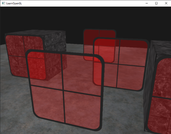
You can find the complete source code with sorting here.
While this approach of sorting the objects by their distance works well for this specific scenario, it doesn't take rotations, scaling or any other transformation into account and weirdly shaped objects need a different metric than simply a position vector.
Sorting objects in your scene is a difficult feat that depends greatly on the type of scene you have, let alone the extra processing power it costs. Completely rendering a scene with solid and transparent objects isn't all that easy. There are more advanced techniques like