


Advanced GLSL
Advanced-OpenGL/Advanced-GLSL
This chapter won't really show you super advanced cool new features that give an enormous boost to your scene's visual quality. This chapter goes more or less into some interesting aspects of GLSL and some nice tricks that may help you in your future endeavors. Basically some good to knows and features that may make your life easier when creating OpenGL applications in combination with GLSL.
We'll discuss some interesting
GLSL's built-in variables
Shaders are extremely pipelined, if we need data from any other source outside of the current shader we'll have to pass data around. We learned to do this via vertex attributes, uniforms, and samplers. There are however a few extra variables defined by GLSL prefixed with gl_ that give us an extra means to gather and/or write data. We've already seen two of them in the chapters so far: gl_Position that is the output vector of the vertex shader, and the fragment shader's gl_FragCoord.
We'll discuss a few interesting built-in input and output variables that are built-in in GLSL and explain how they may benefit us. Note that we won't discuss all built-in variables that exist in GLSL so if you want to see all built-in variables you can check OpenGL's wiki.
Vertex shader variables
We've already seen gl_Position which is the clip-space output position vector of the vertex shader. Setting gl_Position in the vertex shader is a strict requirement if you want to render anything on the screen. Nothing we haven't seen before.
gl_PointSize
One of the render primitives we're able to choose from is GL_POINTS in which case each single vertex is a primitive and rendered as a point. It is possible to set the size of the points being rendered via OpenGL's
One output variable defined by GLSL is called gl_PointSize that is a
Influencing the point sizes in the vertex shader is disabled by default, but if you want to enable this you'll have to enable OpenGL's GL_PROGRAM_POINT_SIZE:
glEnable (GL_PROGRAM_POINT_SIZE);
A simple example of influencing point sizes is by setting the point size equal to the clip-space position's z value which is equal to the vertex's distance to the viewer. The point size should then increase the further we are from the vertices as the viewer.
void main()
{
    gl_Position = projection * view * model * vec4(aPos, 1.0);
    gl_PointSize = gl_Position.z;
}
The result is that the points we've drawn are rendered larger the more we move away from them:
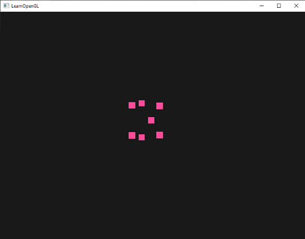
You can imagine that varying the point size per vertex is interesting for techniques like particle generation.
gl_VertexID
The gl_Position and gl_PointSize are output variables since their value is read as output from the vertex shader; we can influence the result by writing to them. The vertex shader also gives us an interesting input variable, that we can only read from, called gl_VertexID.
The integer variable gl_VertexID holds the current ID of the vertex we're drawing. When doing indexed rendering (with
Fragment shader variables
Within the fragment shader we also have access to some interesting variables. GLSL gives us two interesting input variables called gl_FragCoord and gl_FrontFacing.
gl_FragCoord
We've seen the gl_FragCoord a couple of times before during the discussion of depth testing, because the z component of the gl_FragCoord vector is equal to the depth value of that particular fragment. However, we can also use the x and y component of that vector for some interesting effects.
The gl_FragCoord's x and y component are the window- or screen-space coordinates of the fragment, originating from the bottom-left of the window. We specified a render window of 800x600 with x values between 0 and 800, and y values between 0 and 600.
Using the fragment shader we could calculate a different color value based on the screen coordinate of the fragment. A common usage for the gl_FragCoord variable is for comparing visual output of different fragment calculations, as usually seen in tech demos. We could for example split the screen in two by rendering one output to the left side of the window and another output to the right side of the window. An example fragment shader that outputs a different color based on the fragment's screen coordinates is given below:
void main()
{
    if(gl_FragCoord.x < 400)
        FragColor = vec4(1.0, 0.0, 0.0, 1.0);
    else
        FragColor = vec4(0.0, 1.0, 0.0, 1.0);
}
Because the width of the window is equal to 800, whenever a pixel's x-coordinate is less than 400 it must be at the left side of the window and we'll give that fragment a different color.
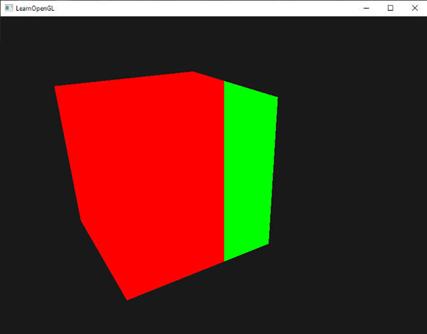
We can now calculate two completely different fragment shader results and display each of them on a different side of the window. This is great for testing out different lighting techniques for example.
gl_FrontFacing
Another interesting input variable in the fragment shader is the gl_FrontFacing variable. In the face culling chapter we mentioned that OpenGL is able to figure out if a face is a front or back face due to the winding order of the vertices. The gl_FrontFacing variable tells us if the current fragment is part of a front-facing or a back-facing face. We could, for example, decide to output different colors for all back faces.
The gl_FrontFacing variable is a true if the fragment is part of a front face and false otherwise. We could create a cube this way with a different texture on the inside than on the outside:
#version 330 core
out vec4 FragColor;

in vec2 TexCoords;

uniform sampler2D frontTexture;
uniform sampler2D backTexture;

void main()
{
    if(gl_FrontFacing)
        FragColor = texture(frontTexture, TexCoords);
    else
        FragColor = texture(backTexture, TexCoords);
}
If we take a peek inside the container we can now see a different texture being used.
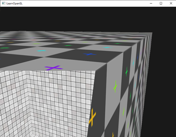
Note that if you enabled face culling you won't be able to see any faces inside the container and using gl_FrontFacing would then be pointless.
gl_FragDepth
The input variable gl_FragCoord is an input variable that allows us to read screen-space coordinates and get the depth value of the current fragment, but it is a
To set the depth value in the shader we write any value between 0.0 and 1.0 to the output variable:
gl_FragDepth = 0.0; // this fragment now has a depth value of 0.0
If the shader does not write anything to gl_FragDepth, the variable will automatically take its value from gl_FragCoord.z.
Setting the depth value manually has a major disadvantage however. That is because OpenGL disables
By writing to gl_FragDepth you should take this performance penalty into consideration. From OpenGL 4.2 however, we can still sort of mediate between both sides by redeclaring the gl_FragDepth variable at the top of the fragment shader with a
layout (depth_<condition>) out float gl_FragDepth;
This condition can take the following values:
| Condition | Description |
|---|---|
any |
The default value. Early depth testing is disabled. |
greater |
You can only make the depth value larger compared to gl_FragCoord.z. |
less |
You can only make the depth value smaller compared to gl_FragCoord.z. |
unchanged |
If you write to gl_FragDepth, you will write exactly gl_FragCoord.z. |
By specifying greater or less as the depth condition, OpenGL can make the assumption that you'll only write depth values larger or smaller than the fragment's depth value. This way OpenGL is still able to do early depth testing when the depth buffer value is part of the other direction of gl_FragCoord.z.
An example of where we increase the depth value in the fragment shader, but still want to preserve some of the early depth testing is shown in the fragment shader below:
#version 420 core // note the GLSL version!
out vec4 FragColor;
layout (depth_greater) out float gl_FragDepth;

void main()
{
    FragColor = vec4(1.0);
    gl_FragDepth = gl_FragCoord.z + 0.1;
}
Do note that this feature is only available from OpenGL version 4.2 or higher.
Interface blocks
So far, every time we sent data from the vertex to the fragment shader we declared several matching input/output variables. Declaring these one at a time is the easiest way to send data from one shader to another, but as applications become larger you probably want to send more than a few variables over.
To help us organize these variables GLSL offers us something called
#version 330 core
layout (location = 0) in vec3 aPos;
layout (location = 1) in vec2 aTexCoords;

uniform mat4 model;
uniform mat4 view;
uniform mat4 projection;

out VS_OUT
{
    vec2 TexCoords;
} vs_out;

void main()
{
    gl_Position = projection * view * model * vec4(aPos, 1.0);
    vs_out.TexCoords = aTexCoords;
}
This time we declared an interface block called vs_out that groups together all the output variables we want to send to the next shader. This is kind of a trivial example, but you can imagine that this helps organize your shaders' inputs/outputs. It is also useful when we want to group shader input/output into arrays as we'll see in the next chapter about geometry shaders.
Then we also need to declare an input interface block in the next shader which is the fragment shader. The
#version 330 core
out vec4 FragColor;

in VS_OUT
{
    vec2 TexCoords;
} fs_in;

uniform sampler2D texture;

void main()
{
    FragColor = texture(texture, fs_in.TexCoords);
}
As long as both interface block names are equal, their corresponding input and output is matched together. This is another useful feature that helps organize your code and proves useful when crossing between certain shader stages like the geometry shader.
Uniform buffer objects
We've been using OpenGL for quite a while now and learned some pretty cool tricks, but also a few annoyances. For example, when using more than one shader we continuously have to set uniform variables where most of them are exactly the same for each shader.
OpenGL gives us a tool called
Because a uniform buffer object is a buffer like any other buffer we can create one via
#version 330 core
layout (location = 0) in vec3 aPos;

layout (std140) uniform Matrices
{
    mat4 projection;
    mat4 view;
};

uniform mat4 model;

void main()
{
    gl_Position = projection * view * model * vec4(aPos, 1.0);
}
In most of our samples we set a projection and view uniform matrix every frame for each shader we're using. This is a perfect example of where uniform buffer objects become useful since now we only have to store these matrices once.
Here we declared a uniform block called Matrices that stores two 4x4 matrices. Variables in a uniform block can be directly accessed without the block name as a prefix. Then we store these matrix values in a buffer somewhere in the OpenGL code and each shader that declares this uniform block has access to the matrices.
You're probably wondering right now what the layout (std140) statement means. What this says is that the currently defined uniform block uses a specific memory layout for its content; this statement sets the
Uniform block layout
The content of a uniform block is stored in a buffer object, which is effectively nothing more than a reserved piece of global GPU memory. Because this piece of memory holds no information on what kind of data it holds, we need to tell OpenGL what parts of the memory correspond to which uniform variables in the shader.
Imagine the following uniform block in a shader:
layout (std140) uniform ExampleBlock
{
    float value;
    vec3  vector;
    mat4  matrix;
    float values[3];
    bool  boolean;
    int   integer;
};
What we want to know is the size (in bytes) and the offset (from the start of the block) of each of these variables so we can place them in the buffer in their respective order. The size of each of the elements is clearly stated in OpenGL and directly corresponds to C++ data types; vectors and matrices being (large) arrays of floats. What OpenGL doesn't clearly state is the
By default, GLSL uses a uniform memory layout called a
While a shared layout gives us some space-saving optimizations, we'd need to query the offset for each uniform variable which translates to a lot of work. The general practice however is to not use the shared layout, but to use the
Each variable has a
The exact layout rules can be found at OpenGL's uniform buffer specification here, but we'll list the most common rules below. Each variable type in GLSL such as N.
| Type | Layout rule |
|---|---|
| Scalar e.g. |
Each scalar has a base alignment of N. |
| Vector | Either 2N or 4N. This means that a |
| Array of scalars or vectors | Each element has a base alignment equal to that of a |
| Matrices | Stored as a large array of column vectors, where each of those vectors has a base alignment of |
| Struct | Equal to the computed size of its elements according to the previous rules, but padded to a multiple of the size of a |
Like most of OpenGL's specifications it's easier to understand with an example. We're taking the uniform block called ExampleBlock we introduced earlier and calculate the aligned offset for each of its members using the std140 layout:
layout (std140) uniform ExampleBlock
{
                     // base alignment  // aligned offset
    float value;     // 4               // 0
    vec3 vector;     // 16              // 16  (offset must be multiple of 16 so 4->16)
    mat4 matrix;     // 16              // 32  (column 0)
                     // 16              // 48  (column 1)
                     // 16              // 64  (column 2)
                     // 16              // 80  (column 3)
    float values[3]; // 16              // 96  (values[0])
                     // 16              // 112 (values[1])
                     // 16              // 128 (values[2])
    bool boolean;    // 4               // 144
    int integer;     // 4               // 148
};
As an exercise, try to calculate the offset values yourself and compare them to this table. With these calculated offset values, based on the rules of the std140 layout, we can fill the buffer with data at the appropriate offsets using functions like
By adding the statement layout (std140) in the definition of the uniform block we tell OpenGL that this uniform block uses the std140 layout. There are two other layouts to choose from that require us to query each offset before filling the buffers. We've already seen the shared layout, with the other remaining layout being packed. When using the packed layout, there is no guarantee that the layout remains the same between programs (not shared) because it allows the compiler to optimize uniform variables away from the uniform block which may differ per shader.
Using uniform buffers
We've defined uniform blocks and specified their memory layout, but we haven't discussed how to actually use them yet.
First, we need to create a uniform buffer object which is done via the familiar
unsigned int uboExampleBlock;
glGenBuffers (1, &uboExampleBlock);
glBindBuffer (GL_UNIFORM_BUFFER, uboExampleBlock);
glBufferData (GL_UNIFORM_BUFFER, 152, NULL, GL_STATIC_DRAW); // allocate 152 bytes of memory
glBindBuffer (GL_UNIFORM_BUFFER, 0);
Now whenever we want to update or insert data into the buffer, we bind to uboExampleBlock and use
In the OpenGL context there is a number of
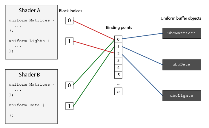
As you can see we can bind multiple uniform buffers to different binding points. Because shader A and shader B both have a uniform block linked to the same binding point 0, their uniform blocks share the same uniform data found in uboMatrices; a requirement being that both shaders defined the same Matrices uniform block.
To set a shader uniform block to a specific binding point we call 2 as follows:
unsigned int lights_index = glGetUniformBlockIndex (shaderA.ID, "Lights");
glUniform BlockBindingNote that we have to repeat this process for each shader.
layout(std140, binding = 2) uniform Lights { ... };
Then we also need to bind the uniform buffer object to the same binding point and this can be accomplished with either
glBindBuffer BaseglBindBuffer Range
The function 2; from this point on, both sides of the binding point are linked. You can also use
Now that everything is set up, we can start adding data to the uniform buffer. We could add all the data as a single byte array, or update parts of the buffer whenever we feel like it using
glBindBuffer (GL_UNIFORM_BUFFER, uboExampleBlock);
int b = true; // bools in GLSL are represented as 4 bytes, so we store it in an integer
glBufferSubData (GL_UNIFORM_BUFFER, 144, 4, &b);
glBindBuffer (GL_UNIFORM_BUFFER, 0);
And the same procedure applies for all the other uniform variables inside the uniform block, but with different range arguments.
A simple example
So let's demonstrate a real example of uniform buffer objects. If we look back at all the previous code samples we've continually been using 3 matrices: the projection, view and model matrix. Of all those matrices, only the model matrix changes frequently. If we have multiple shaders that use this same set of matrices, we'd probably be better off using uniform buffer objects.
We're going to store the projection and view matrix in a uniform block called Matrices. We're not going to store the model matrix in there since the model matrix tends to change frequently between shaders, so we wouldn't really benefit from uniform buffer objects.
#version 330 core
layout (location = 0) in vec3 aPos;

layout (std140) uniform Matrices
{
    mat4 projection;
    mat4 view;
};
uniform mat4 model;

void main()
{
    gl_Position = projection * view * model * vec4(aPos, 1.0);
}
Not much going on here, except that we now use a uniform block with a std140 layout. What we're going to do in our sample application is display 4 cubes where each cube is displayed with a different shader program. Each of the 4 shader programs uses the same vertex shader, but has a unique fragment shader that only outputs a single color that differs per shader.
First, we set the uniform block of the vertex shaders equal to binding point 0. Note that we have to do this for each shader:
unsigned int uniformBlockIndexRed = glGetUniformBlockIndex (shaderRed.ID, "Matrices");
unsigned int uniformBlockIndexGreen = glGetUniformBlockIndex (shaderGreen.ID, "Matrices");
unsigned int uniformBlockIndexBlue = glGetUniformBlockIndex (shaderBlue.ID, "Matrices");
unsigned int uniformBlockIndexYellow = glGetUniformBlockIndex (shaderYellow.ID, "Matrices");
glUniform BlockBindingglUniform BlockBindingglUniform BlockBindingglUniform BlockBinding
Next we create the actual uniform buffer object and bind that buffer to binding point 0:
unsigned int uboMatrices
glGenBuffers (1, &uboMatrices);
glBindBuffer (GL_UNIFORM_BUFFER, uboMatrices);
glBufferData (GL_UNIFORM_BUFFER, 2 * sizeof(glm::mat4), NULL, GL_STATIC_DRAW);
glBindBuffer (GL_UNIFORM_BUFFER, 0);
glBindBuffer Range
First we allocate enough memory for our buffer which is equal to 2 times the size of 0.
Now all that's left to do is fill the buffer. If we keep the field of view value constant of the projection matrix (so no more camera zoom) we only have to update it once in our application - this means we only have to insert this into the buffer only once as well. Because we already allocated enough memory in the buffer object we can use
glm::mat4 projection = glm::perspective (glm::radians (45.0f), (float)width/(float)height, 0.1f, 100.0f);
glBindBuffer (GL_UNIFORM_BUFFER, uboMatrices);
glBufferSubData (GL_UNIFORM_BUFFER, 0, sizeof(glm::mat4), glm::value_ptr(projection));
glBindBuffer (GL_UNIFORM_BUFFER, 0);
Here we store the first half of the uniform buffer with the projection matrix. Then before we render the objects each frame we update the second half of the buffer with the view matrix:
glm::mat4 view = camera.GetViewMatrix();
glBindBuffer (GL_UNIFORM_BUFFER, uboMatrices);
glBufferSubData (GL_UNIFORM_BUFFER, sizeof(glm::mat4), sizeof(glm::mat4), glm::value_ptr(view));
glBindBuffer (GL_UNIFORM_BUFFER, 0);
And that's it for uniform buffer objects. Each vertex shader that contains a Matrices uniform block will now contain the data stored in uboMatrices. So if we now were to draw 4 cubes using 4 different shaders, their projection and view matrix should be the same:
glBindVertexArray (cubeVAO);
shaderRed.use();
glm::mat4 model = glm::mat4(1.0f);
model = glm::translate (model, glm::vec3(-0.75f, 0.75f, 0.0f)); // move top-left
shaderRed.setMat4("model", model);
glDrawArrays (GL_TRIANGLES, 0, 36);
// ... draw Green Cube
// ... draw Blue Cube
// ... draw Yellow Cube
The only uniform we still need to set is the model uniform. Using uniform buffer objects in a scenario like this saves us from quite a few uniform calls per shader. The result looks something like this:
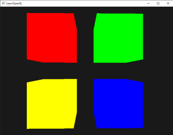
Each of the cubes is moved to one side of the window by translating the model matrix and, thanks to the different fragment shaders, their colors differ per object. This is a relatively simple scenario of where we could use uniform buffer objects, but any large rendering application can have over hundreds of shader programs active which is where uniform buffer objects really start to shine.
You can find the full source code of the uniform example application here.
Uniform buffer objects have several advantages over single uniforms. First, setting a lot of uniforms at once is faster than setting multiple uniforms one at a time. Second, if you want to change the same uniform over several shaders, it is much easier to change a uniform once in a uniform buffer. One last advantage that is not immediately apparent is that you can use a lot more uniforms in shaders using uniform buffer objects. OpenGL has a limit to how much uniform data it can handle which can be queried with GL_MAX_VERTEX_UNIFORM_COMPONENTS. When using uniform buffer objects, this limit is much higher. So whenever you reach a maximum number of uniforms (when doing skeletal animation for example) there's always uniform buffer objects.