


Parallax Mapping
Advanced-Lighting/Parallax-Mapping
Parallax mapping is a technique similar to normal mapping, but based on different principles. Just like normal mapping it is a technique that significantly boosts a textured surface's detail and gives it a sense of depth. While also an illusion, parallax mapping is a lot better in conveying a sense of depth and together with normal mapping gives incredibly realistic results. While parallax mapping isn't necessarily a technique directly related to (advanced) lighting, I'll still discuss it here as the technique is a logical follow-up of normal mapping. Note that getting an understanding of normal mapping, specifically tangent space, is strongly advised before learning parallax mapping.
Parallax mapping is closely related to the family of
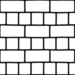
When spanned over a plane, each vertex is displaced based on the sampled height value in the height map, transforming a flat plane to a rough bumpy surface based on a material's geometric properties. For instance, taking a flat plane displaced with the above heightmap results in the following image:
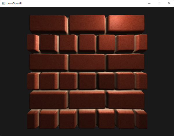
A problem with displacing vertices this way is that a plane needs to contain a huge amount of triangles to get a realistic displacement, otherwise the displacement looks too blocky. As each flat surface may then require over 10000 vertices this quickly becomes computationally infeasible. What if we could somehow achieve similar realism without the need of extra vertices? In fact, what if I were to tell you that the previously shown displaced surface is actually rendered with only 2 triangles. This brick surface shown is rendered with
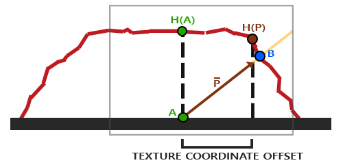
The idea behind parallax mapping is to alter the texture coordinates in such a way that it looks like a fragment's surface is higher or lower than it actually is, all based on the view direction and a heightmap. To understand how it works, take a look at the following image of our brick surface:

Here the rough red line represents the values in the heightmap as the geometric surface representation of the brick surface and the vector \(\color{orange}{\bar{V}}\) represents the surface to view direction (viewDir). If the plane would have actual displacement, the viewer would see the surface at point \(\color{blue}B\). However, as our plane has no actual displacement the view direction is calculated from point \(\color{green}A\) as we'd expect. Parallax mapping aims to offset the texture coordinates at fragment position \(\color{green}A\) in such a way that we get texture coordinates at point \(\color{blue}B\). We then use the texture coordinates at point \(\color{blue}B\) for all subsequent texture samples, making it look like the viewer is actually looking at point \(\color{blue}B\).
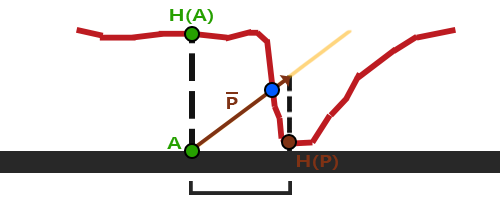
The trick is to figure out how to get the texture coordinates at point \(\color{blue}B\) from point \(\color{green}A\). Parallax mapping tries to solve this by scaling the fragment-to-view direction vector \(\color{orange}{\bar{V}}\) by the height at fragment \(\color{green}A\). So we're scaling the length of \(\color{orange}{\bar{V}}\) to be equal to a sampled value from the heightmap \(\color{green}{H(A)}\) at fragment position \(\color{green}A\). The image below shows this scaled vector \(\color{brown}{\bar{P}}\):
We then take this vector \(\color{brown}{\bar{P}}\) and take its vector coordinates that align with the plane as the texture coordinate offset. This works because vector \(\color{brown}{\bar{P}}\) is calculated using a height value from the heightmap. So the higher a fragment's height, the more it effectively gets displaced.
This little trick gives good results most of the time, but it is still a really crude approximation to get to point \(\color{blue}B\). When heights change rapidly over a surface the results tend to look unrealistic as the vector \(\color{brown}{\bar{P}}\) will not end up close to \(\color{blue}B\) as you can see below:
Another issue with parallax mapping is that it's difficult to figure out which coordinates to retrieve from \(\color{brown}{\bar{P}}\) when the surface is arbitrarily rotated in some way. We'd rather do this in a different coordinate space where the x and y component of vector \(\color{brown}{\bar{P}}\) always align with the texture's surface. If you've followed along in the normal mapping chapter you probably guessed how we can accomplish this. And yes, we would like to do parallax mapping in tangent space.
By transforming the fragment-to-view direction vector \(\color{orange}{\bar{V}}\) to tangent space, the transformed \(\color{brown}{\bar{P}}\) vector will have its x and y component aligned to the surface's tangent and bitangent vectors. As the tangent and bitangent vectors are pointing in the same direction as the surface's texture coordinates we can take the x and y components of \(\color{brown}{\bar{P}}\) as the texture coordinate offset, regardless of the surface's orientation.
But enough about the theory, let's get our feet wet and start implementing actual parallax mapping.
Parallax mapping
For parallax mapping we're going to use a simple 2D plane for which we calculated its tangent and bitangent vectors before sending it to the GPU; similar to what we did in the normal mapping chapter. Onto the plane we're going to attach a diffuse texture, a normal map, and a displacement map that you can download from their urls. For this example we're going to use parallax mapping in conjunction with normal mapping. Because parallax mapping gives the illusion of displacing a surface, the illusion breaks when the lighting doesn't match. As normal maps are often generated from heightmaps, using a normal map together with the heightmap makes sure the lighting is in place with the displacement.
You may have already noted that the displacement map linked above is the inverse of the heightmap shown at the start of this chapter. With parallax mapping it makes more sense to use the inverse of the heightmap as it's easier to fake depth than height on flat surfaces. This slightly changes how we perceive parallax mapping as shown below:
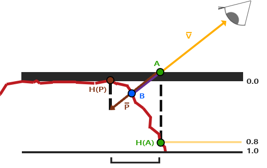
We again have a points \(\color{green}A\) and \(\color{blue}B\), but this time we obtain vector \(\color{brown}{\bar{P}}\) by subtracting vector \(\color{orange}{\bar{V}}\) from the texture coordinates at point \(\color{green}A\). We can obtain depth values instead of height values by subtracting the sampled heightmap values from 1.0 in the shaders, or by simply inversing its texture values in image-editing software as we did with the depthmap linked above.
Parallax mapping is implemented in the fragment shader as the displacement effect is different all over a triangle's surface. In the fragment shader we're then going to need to calculate the fragment-to-view direction vector \(\color{orange}{\bar{V}}\) so we need the view position and a fragment position in tangent space. In the normal mapping chapter we already had a vertex shader that sends these vectors in tangent space so we can take an exact copy of that chapter's vertex shader:
#version 330 core
layout (location = 0) in vec3 aPos;
layout (location = 1) in vec3 aNormal;
layout (location = 2) in vec2 aTexCoords;
layout (location = 3) in vec3 aTangent;
layout (location = 4) in vec3 aBitangent;

out VS_OUT {
    vec3 FragPos;
    vec2 TexCoords;
    vec3 TangentLightPos;
    vec3 TangentViewPos;
    vec3 TangentFragPos;
} vs_out;

uniform mat4 projection;
uniform mat4 view;
uniform mat4 model;

uniform vec3 lightPos;
uniform vec3 viewPos;

void main()
{
    gl_Position      = projection * view * model * vec4(aPos, 1.0);
    vs_out.FragPos   = vec3(model * vec4(aPos, 1.0));
    vs_out.TexCoords = aTexCoords;

    vec3 T   = normalize(mat3(model) * aTangent);
    vec3 B   = normalize(mat3(model) * aBitangent);
    vec3 N   = normalize(mat3(model) * aNormal);
    mat3 TBN = transpose(mat3(T, B, N));

    vs_out.TangentLightPos = TBN * lightPos;
    vs_out.TangentViewPos  = TBN * viewPos;
    vs_out.TangentFragPos  = TBN * vs_out.FragPos;
}
Within the fragment shader we then implement the parallax mapping logic. The fragment shader looks a bit like this:
#version 330 core
out vec4 FragColor;

in VS_OUT {
    vec3 FragPos;
    vec2 TexCoords;
    vec3 TangentLightPos;
    vec3 TangentViewPos;
    vec3 TangentFragPos;
} fs_in;

uniform sampler2D diffuseMap;
uniform sampler2D normalMap;
uniform sampler2D depthMap;

uniform float height_scale;

vec2 ParallaxMapping(vec2 texCoords, vec3 viewDir);

void main()
{
    // offset texture coordinates with Parallax Mapping
    vec3 viewDir   = normalize(fs_in.TangentViewPos - fs_in.TangentFragPos);
    vec2 texCoords = ParallaxMapping(fs_in.TexCoords,  viewDir);

    // then sample textures with new texture coords
    vec3 diffuse = texture(diffuseMap, texCoords);
    vec3 normal  = texture(normalMap, texCoords);
    normal = normalize(normal * 2.0 - 1.0);
    // proceed with lighting code
    [...]
}
We defined a function called
Let's take a look inside the
vec2 ParallaxMapping(vec2 texCoords, vec3 viewDir)
{
    float height =  texture(depthMap, texCoords).r;
    vec2 p = viewDir.xy / viewDir.z * (height * height_scale);
    return texCoords - p;
}
This relatively simple function is a direct translation of what we've discussed so far. We take the original texture coordinates texCoords and use these to sample the height (or depth) from the depthMap at the current fragment \(\color{green}{A}\) as \(\color{green}{H(A)}\). We then calculate \(\color{brown}{\bar{P}}\) as the x and y component of the tangent-space viewDir vector divided by its z component and scaled by \(\color{green}{H(A)}\). We also introduced a height_scale uniform for some extra control as the parallax effect is usually too strong without an extra scale parameter. We then subtract this vector \(\color{brown}{\bar{P}}\) from the texture coordinates to get the final displaced texture coordinates.
What is interesting to note here is the division of viewDir.xy by viewDir.z. As the viewDir vector is normalized, viewDir.z will be somewhere in the range between 0.0 and 1.0. When viewDir is largely parallel to the surface, its z component is close to 0.0 and the division returns a much larger vector \(\color{brown}{\bar{P}}\) compared to when viewDir is largely perpendicular to the surface. We're adjusting the size of \(\color{brown}{\bar{P}}\) in such a way that it offsets the texture coordinates at a larger scale when looking at a surface from an angle compared to when looking at it from the top; this gives more realistic results at angles.
Some prefer to leave the division by viewDir.z out of the equation as default Parallax Mapping could produce undesirable results at angles; the technique is then called
The resulting texture coordinates are then used to sample the other textures (diffuse and normal) and this gives a very neat displaced effect as you can see below with a height_scale of roughly 0.1:
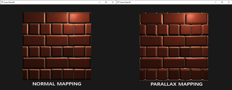
Here you can see the difference between normal mapping and parallax mapping combined with normal mapping. Because parallax mapping tries to simulate depth it is actually possible to have bricks overlap other bricks based on the direction you view them.
You can still see a few weird border artifacts at the edge of the parallax mapped plane. This happens because at the edges of the plane the displaced texture coordinates can oversample outside the range [0, 1]. This gives unrealistic results based on the texture's wrapping mode(s). A cool trick to solve this issue is to discard the fragment whenever it samples outside the default texture coordinate range:
texCoords = ParallaxMapping(fs_in.TexCoords,  viewDir);
if(texCoords.x > 1.0 || texCoords.y > 1.0 || texCoords.x < 0.0 || texCoords.y < 0.0)
    discard;
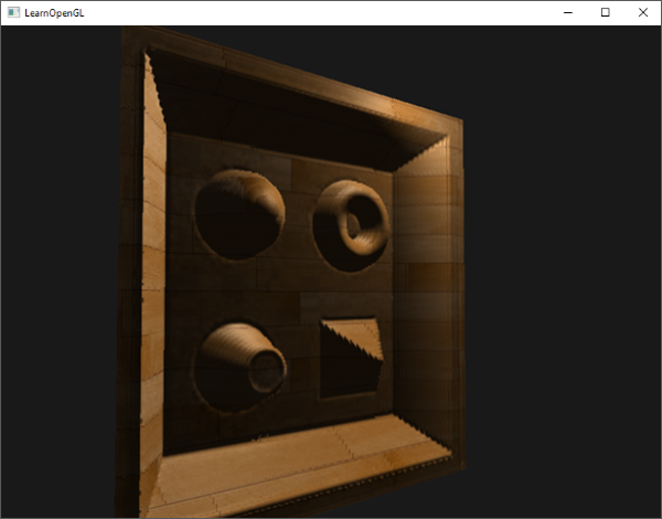
All fragments with (displaced) texture coordinates outside the default range are discarded and Parallax Mapping then gives proper result around the edges of a surface. Note that this trick doesn't work on all types of surfaces, but when applied to a plane it gives great results:
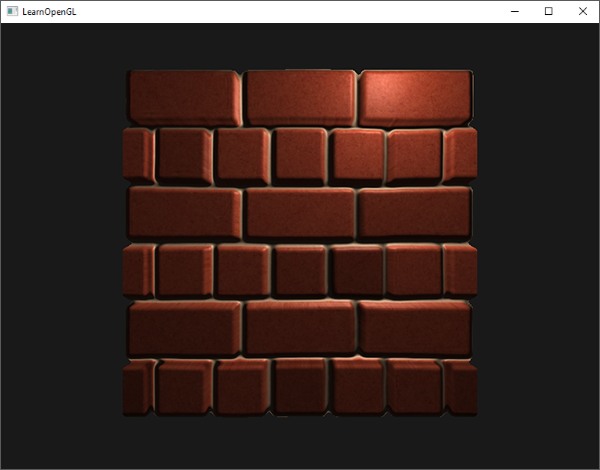
You can find the source code here.
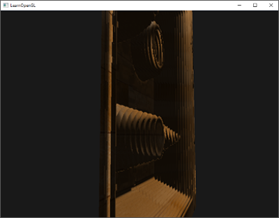
It looks great and is quite fast as well as we only need a single extra texture sample for parallax mapping to work. It does come with a few issues though as it sort of breaks down when looking at it from an angle (similar to normal mapping) and gives incorrect results with steep height changes, as you can see below:
The reason that it doesn't work properly at times is that it's just a crude approximation of displacement mapping. There are some extra tricks however that still allows us to get almost perfect results with steep height changes, even when looking at an angle. For instance, what if we instead of one sample take multiple samples to find the closest point to \(\color{blue}B\)?
Steep Parallax Mapping
Steep Parallax Mapping is an extension on top of Parallax Mapping in that it uses the same principles, but instead of 1 sample it takes multiple samples to better pinpoint vector \(\color{brown}{\bar{P}}\) to \(\color{blue}B\). This gives much better results, even with steep height changes, as the accuracy of the technique is improved by the number of samples.
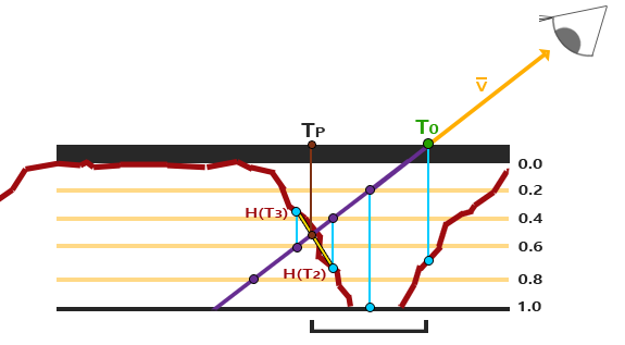
The general idea of Steep Parallax Mapping is that it divides the total depth range into multiple layers of the same height/depth. For each of these layers we sample the depthmap, shifting the texture coordinates along the direction of \(\color{brown}{\bar{P}}\), until we find a sampled depth value that is less than the depth value of the current layer. Take a look at the following image:
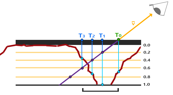
We traverse the depth layers from the top down and for each layer we compare its depth value to the depth value stored in the depthmap. If the layer's depth value is less than the depthmap's value it means this layer's part of vector \(\color{brown}{\bar{P}}\) is not below the surface. We continue this process until the layer's depth is higher than the value stored in the depthmap: this point is then below the (displaced) geometric surface.
In this example we can see that the depthmap value at the second layer (D(2) = 0.73) is lower than the second layer's depth value 0.4 so we continue. In the next iteration, the layer's depth value 0.6 is higher than the depthmap's sampled depth value (D(3) = 0.37). We can thus assume vector \(\color{brown}{\bar{P}}\) at the third layer to be the most viable position of the displaced geometry. We then take the texture coordinate offset \(T_3\) from vector \(\color{brown}{\bar{P_3}}\) to displace the fragment's texture coordinates. You can see how the accuracy increases with more depth layers.
To implement this technique we only have to change the
vec2 ParallaxMapping(vec2 texCoords, vec3 viewDir)
{
    // number of depth layers
    const float numLayers = 10;
    // calculate the size of each layer
    float layerDepth = 1.0 / numLayers;
    // depth of current layer
    float currentLayerDepth = 0.0;
    // the amount to shift the texture coordinates per layer (from vector P)
    vec2 P = viewDir.xy * height_scale;
    vec2 deltaTexCoords = P / numLayers;

    [...]
}
Here we first set things up: we specify the number of layers, calculate the depth offset of each layer, and finally calculate the texture coordinate offset that we have to shift along the direction of \(\color{brown}{\bar{P}}\) per layer.
We then iterate through all the layers, starting from the top, until we find a depthmap value less than the layer's depth value:
// get initial values
vec2  currentTexCoords     = texCoords;
float currentDepthMapValue = texture(depthMap, currentTexCoords).r;

while(currentLayerDepth < currentDepthMapValue)
{
    // shift texture coordinates along direction of P
    currentTexCoords -= deltaTexCoords;
    // get depthmap value at current texture coordinates
    currentDepthMapValue = texture(depthMap, currentTexCoords).r;
    // get depth of next layer
    currentLayerDepth += layerDepth;
}

return currentTexCoords;
Here we loop over each depth layer and stop until we find the texture coordinate offset along vector \(\color{brown}{\bar{P}}\) that first returns a depth that's below the (displaced) surface. The resulting offset is subtracted from the fragment's texture coordinates to get a final displaced texture coordinate vector, this time with much more accuracy compared to traditional parallax mapping.
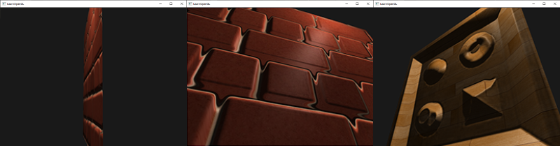
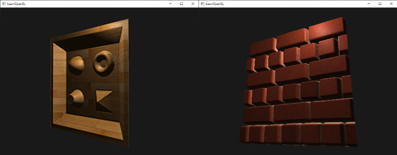
With around 10 samples the brick surface already looks more viable even when looking at it from an angle, but steep parallax mapping really shines when having a complex surface with steep height changes; like the earlier displayed wooden toy surface:
We can improve the algorithm a bit by exploiting one of Parallax Mapping's properties. When looking straight onto a surface there isn't much texture displacement going on while there is a lot of displacement when looking at a surface from an angle (visualize the view direction on both cases). By taking less samples when looking straight at a surface and more samples when looking at an angle we only sample the necessary amount:
const float minLayers = 8.0;
const float maxLayers = 32.0;
float numLayers = mix(maxLayers, minLayers, max(dot(vec3(0.0, 0.0, 1.0), viewDir), 0.0));
Here we take the dot product of viewDir and the positive z direction and use its result to align the number of samples to minLayers or maxLayers based on the angle we're looking towards a surface (note that the positive z direction equals the surface's normal vector in tangent space). If we were to look at a direction parallel to the surface we'd use a total of 32 layers.
You can find the updated source code here. You can also find the wooden toy box surface here: diffuse, normal and depth.
Steep Parallax Mapping also comes with its problems though. Because the technique is based on a finite number of samples, we get aliasing effects and the clear distinctions between layers can easily be spotted:
We can reduce the issue by taking a larger number of samples, but this quickly becomes too heavy a burden on performance. There are several approaches that aim to fix this issue by not taking the first position that's below the (displaced) surface, but by interpolating between the position's two closest depth layers to find a much closer match to \(\color{blue}B\).
Two of the more popular of these approaches are called
Parallax Occlusion Mapping
Parallax Occlusion Mapping is based on the same principles as Steep Parallax Mapping, but instead of taking the texture coordinates of the first depth layer after a collision, we're going to linearly interpolate between the depth layer after and before the collision. We base the weight of the linear interpolation on how far the surface's height is from the depth layer's value of both layers. Take a look at the following picture to get a grasp of how it works:
As you can see, it's largely similar to Steep Parallax Mapping with as an extra step the linear interpolation between the two depth layers' texture coordinates surrounding the intersected point. This is again an approximation, but significantly more accurate than Steep Parallax Mapping.
The code for Parallax Occlusion Mapping is an extension on top of Steep Parallax Mapping and not too difficult:
[...] // steep parallax mapping code here

// get texture coordinates before collision (reverse operations)
vec2 prevTexCoords = currentTexCoords + deltaTexCoords;

// get depth after and before collision for linear interpolation
float afterDepth  = currentDepthMapValue - currentLayerDepth;
float beforeDepth = texture(depthMap, prevTexCoords).r - currentLayerDepth + layerDepth;

// interpolation of texture coordinates
float weight = afterDepth / (afterDepth - beforeDepth);
vec2 finalTexCoords = prevTexCoords * weight + currentTexCoords * (1.0 - weight);

return finalTexCoords;
After we found the depth layer after intersecting the (displaced) surface geometry, we also retrieve the texture coordinates of the depth layer before intersection. Then we calculate the distance of the (displaced) geometry's depth from the corresponding depth layers and interpolate between these two values. The linear interpolation is a basic interpolation between both layer's texture coordinates. The function then finally returns the final interpolated texture coordinates.
Parallax Occlusion Mapping gives surprisingly good results and although some slight artifacts and aliasing issues are still visible, it's a generally a good trade-off and only really visible when heavily zoomed in or looking at very steep angles.
You can find the source code here.
Parallax Mapping is a great technique to boost the detail of your scene, but does come with a few artifacts you'll have to consider when using it. Most often, parallax mapping is used on floor or wall-like surfaces where it's not as easy to determine the surface's outline and the viewing angle is most often roughly perpendicular to the surface. This way, the artifacts of Parallax Mapping aren't as noticeable and make it an incredibly interesting technique for boosting your objects' details.
Additional resources
- Parallax Occlusion Mapping in GLSL: great parallax mapping tutorial by sunandblackcat.com.
- How Parallax Displacement Mapping Works: a nice video tutorial of how parallax mapping works by TheBennyBox.